Download
1 / 24
250 likes | 433 Vues
Fixed-gain CMOS Differential Amplifiers for the 40 K to 390 K Temperature Range. Vratislav MICHAL , Alain J. KREISLER and Annick F. DÉGARDIN Paris Electrical Engineering Laboratory (LGEP) , Gif sur Yvette, France Supélec; CNRS UMR 8507; UPMC - Univ Paris 06; Univ Paris Sud 11

E N D
Fixed-gain CMOS Differential Amplifiers for the 40 K to 390 K Temperature Range Vratislav MICHAL, Alain J. KREISLER and Annick F. DÉGARDIN Paris Electrical Engineering Laboratory (LGEP), Gif sur Yvette, France Supélec; CNRS UMR 8507; UPMC - Univ Paris 06; Univ Paris Sud 11 Geoffroy KLISNICK, Gérard SOU and Michel REDON Electronics and Electromagnetism Laboratory (L2E), UPMC - Univ Paris 06 , 4 place Jussieu, Paris, France Research supported by a Marie Curie Early Stage Research Training Fellowship of the European Community’s Sixth Framework Programme under contract number MEST-CT-2005-020692
Outline • Our objectives • Introduction / design approach • First design & results • Second design & results • Conclusions Vratislav Michal - Wolte 8, 22-25July 2008, Ilmenau
I. Our objectives Vratislav Michal - Wolte 8, 22-25July 2008, Ilmenau
Goals of the project • Development of wide temperature range CMOS readout amplifiers for YBaCuO bolometric detectors: • Room temperature semiconducting • Superconducting Requirements: • 40 dB, accurate static gain, • 77 K to 300 K temperature range, • Differential gain BW: DC to several MHz, • Low noise operation, • High (> 100kΩ) input impedance, • Low power consumption, • Simple architecture. Low noise Differential CMOS amplifier Vratislav Michal - Wolte 8, 22-25July 2008, Ilmenau
II. Introduction / design approach Vratislav Michal - Wolte 8, 22-25July 2008, Ilmenau
Four pixel configuration: differential amplification • Structure of cascaded amplifier asymmetrical (Rbi is the steady state pixel resistance), • b) Selected differential read-out technique. Vratislav Michal - Wolte 8, 22-25July 2008, Ilmenau
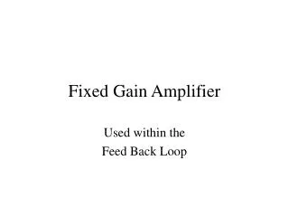
II.1 Closed loop differential amplifiers • Currently, fixed gain amplifiers are realized as closed-loop networks with resistor feedback (differential amplifier, instrumentation amplifier etc.) • Thermal noise of resistors can be dominant! • Frequency compensation degrade the GBW and SR Vratislav Michal - Wolte 8, 22-25July 2008, Ilmenau
II.2 In-structure fixed gain (CMOS) • + No resistors in the structure simplification and silicon surface save, reduced noise contribution • + Absence of feedback improves the time characteristics (no stability problems), increases the BW and reduces the power consumption • - Linearity, distortion • - No developed architectures * * Bolometer noise voltage is neglected Vratislav Michal - Wolte 8, 22-25July 2008, Ilmenau
II.3 Open loop amplifiers: design approach (a)(b) Gain is given by transistors geometry ratio Gain is given by ratio of gmx of OTA For current biased MOS architectures, the transconductance is given by: The 40dB gain can require the geometric ratio value of transistors up to 10 000×KP/KN! Vratislav Michal - Wolte 8, 22-25July 2008, Ilmenau
II.4 Adopted technique Decreasing the transconductance by current sink [PhD F. Voisin, 2005] MOS diode transconductance given by Proposed method for decreasing the transconductance by means of current scaling: Current difference makes the function very sensitive: Vratislav Michal - Wolte 8, 22-25July 2008, Ilmenau
III. First design & results Vratislav Michal - Wolte 8, 22-25July 2008, Ilmenau
III.1 Design of 1st folded cascode amplifier in AMS 0.35µm • DC transfer characteristic: • Gain is the slope of the DC transfer characteristic: where: Vratislav Michal - Wolte 8, 22-25July 2008, Ilmenau
III.3 Measured DC and AC characteristics of 1st amplifier AC response and input noise (VDD=5V, IQ=2mA) DC transfer characteristic at 290 K • Simple fixed gain architecture: suitable for low noise and large BW operation, • Gain is fixed by means of geometric ratio: no variation with temperature, • Linearity is good for small signals, • DC transfer characteristic √Vin. Vratislav Michal - Wolte 8, 22-25July 2008, Ilmenau
IV. Second design & results Vratislav Michal - Wolte 8, 22-25July 2008, Ilmenau
IV.1 2nd amplifier: Linearization of DC transfer characteristic Based on cancelling the quadratic terms in the basic equation of the MOS transistor. The node equation can be written: The extraction of output voltage leads to (assuming β1 = β2, VTH1 = VTH2): Vratislav Michal - Wolte 8, 22-25July 2008, Ilmenau
IV.2 Analysis of transfer function, temperature properties • DC transfer function: • We replace the elements without temperature dependence by C: • Which leads to: • Gain is given by derivation: Vratislav Michal - Wolte 8, 22-25July 2008, Ilmenau
IV.4 DC transfer characteristic Temperature compensated linear amplifier for three VDD values (2nd amplifier type) DC measured transfer characteristic and measured voltage gain @ 2.5V,290 K Vratislav Michal - Wolte 8, 22-25July 2008, Ilmenau
IV.5 Cryogenic tests: DC Vout [V] Vout [V] Vin [V] Vin [V] DC transfer characteristic for two DC supply values (2nd type linear amplifier) Vratislav Michal - Wolte 8, 22-25July 2008, Ilmenau
V. Conclusions Vratislav Michal - Wolte 8, 22-25July 2008, Ilmenau
V.1 Comparison with industrial state of the art Key parameters of developed amplifiers Industrial differential amplifiers (room temperature) Vratislav Michal - Wolte 8, 22-25July 2008, Ilmenau
V.2 Summary • Two amplifiers, based on different techniques of gain setting, have been designed, fabricated and characterized by measurements in a wide temperature range. • Both amplifiers exhibit very good performances, competitive with or superior to the industrial state-of-the-art. • Small size and low consumption make them ideal as versatile blocks for VLSI integration. • Wide temperature range operation demonstrates robustness of the design. Vratislav Michal - Wolte 8, 22-25July 2008, Ilmenau
V.3 PCB test board with integrated ASIC Vratislav Michal - Wolte 8, 22-25July 2008, Ilmenau
Appendix I: Differential (type I) amplifier designed for 40dB voltage gain Vratislav Michal - Wolte 8, 22-25July 2008, Ilmenau
Appendix II: CMOS AMS 0.35µm realization of type II amplifier Schematic view of designed amplifier Vratislav Michal - Wolte 8, 22-25July 2008, Ilmenau


![Dictée for Week 15 [ c = k , qu = k , k = k ]](https://cdn2.slideserve.com/5052370/dict-e-for-week-15-c-k-qu-k-k-k-dt.jpg)