Download
1 / 6
70 likes | 84 Vues
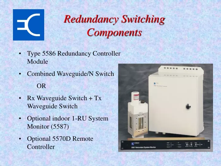
Redundancy Switching Components. Type 5586 Redundancy Controller Module Combined Waveguide/N Switch OR Rx Waveguide Switch + Tx Waveguide Switch Optional indoor 1-RU System Monitor (5587) Optional 5570D Remote Controller. Low Power Redundancy.

E N D
Redundancy Switching Components • Type 5586 Redundancy Controller Module • Combined Waveguide/N Switch • OR • Rx Waveguide Switch + Tx Waveguide Switch • Optional indoor 1-RU System Monitor (5587) • Optional 5570D Remote Controller
Low Power Redundancy • The 5W, 10W, 20W, 30W and 40W transceiver can be either mounted on the antenna boom or the antenna pedestal. • Standard mounting kitsupplied is designed to bemounted on the antenna boom • The 5586 RedundancyController and the two5582 Mains Power Suppliesare mounted on the antennapedestal
High Power Redundancy • The 60W or 120W mounting hardware is designed to be mounted to the antenna pedestal with the 5586 Redundancy Controller
5587 Redundancy Monitor • Duplication of the 5586 Redundancy Controller internal switches and LED indicators. • 1RU high assembly • Provides summary alarm for each stream and RF switches • Allows forced switch over between streams • Power is supplied from the Redundancy Controller through the interface cable up to 100m.
Dual 5570 Remote Controller • Full function, permanently-installed, configuration, monitor & control and maintenance. • 2RU high may be “piggy-backed” to the 5587 C-Series Indoor Monitor. • Power is supplied from the Redundancy Controller through the interface cable.
Indoor AC Power 5582 PSU 48V DC 5570D Remote Controller Tx RF Tx RF O/P 5700 Converter Power Control SSPA Rx RF 48V DC M&C 5587 Redundancy Monitor LNA Rx IF Tx IF 5586 Redundancy Controller Rx switch control M&C Cable Blanking Plate OMT Tx switch control LNA Rx IF Termination Modem or other equipment Tx IF 48V DC M&C Rx RF 5700 Converter Power Control SSPA Tx RF O/P 5582 PSU 48V DC Tx RF AC Power Redundant Block Diagram Outdoor Tx RF O/P