Download
1 / 15
160 likes | 224 Vues
Using Nastran and Matlab to Predict Surface Figure Error of a Spherical Mirror. Chris Chrzanowski Charles Frohlich Swales Aerospace, Inc. 5050 Powder Mill Rd. Beltsville, MD, 20705, USA CChrzanowski@swales.com CFrohlich@swales.com. C/SiC Mirror. Introduction.

E N D
Using Nastran and Matlab to Predict Surface Figure Error of a Spherical Mirror Chris Chrzanowski Charles Frohlich Swales Aerospace, Inc. 5050 Powder Mill Rd. Beltsville, MD, 20705, USA CChrzanowski@swales.com CFrohlich@swales.com
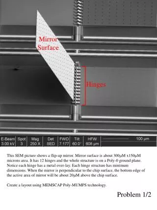
C/SiC Mirror Introduction 1: Silicon Carbide (SiC), coated with SiC CVD 2: Carbon-reinforced Silicon Carbide (C/SiC), coated with Si-SiC CVD • Spherical optical surface, ROC = 600mm • Polished to microroughness of 3.5 nm RMS • Lightweighted aft surface • Integral mount • C/SiC mounting plate also provided as an interface to the integral mount • Two non-flight prototype mirrors for use on the JWST/NIRSpec instrument were received from Galileo Avionica (Florence, Italy), for optical testing at NASA/Goddard Space Flight Center
Goals • Design and build a mount to hold each mirror in a cryogenic dewar • Hold in horizontal orientation (gravity perpendicular to optical axis) • Maintain high thermal conductivity between mirror and dewar cold plate when cooling from room temperature to 20K • Minimize surface figure error (SFE) induced by CTE mismatches among the materials; SiC and C/SiC have a very low CTE at cryo temperatures • Use finite element analysis (FEA) in MSC.NASTRAN 2001 to predict the deformed mirror shapes • Optical post-processing • SigFit: characterize surface with Zernike polynomials for optical analysis • Matlab: “best fit sphere” function to calculate SFE • For this project, SFE defined as the deviation from a perfect sphere
Kinematic Mount Design • Three low-friction ball bearings in a 3-2-1 configuration rest on a conical seat, V-groove, and flat surface, respectively • Spring plungers preload the bearings to support the weight of the mirror in the horizontal configuration • Kinematically constrains the mirror in six degrees of freedom (DOF), allowing the mirror to expand or contract, isolated from the CTE mismatch of the Copper cold plate
Kinematic Mount Design • Low-stress Copper thermal straps used for thermal conductivity • Belleville spring washers used on each fastener stack to maintain preload when going cold, or to prevent fastener from compressing mirror material SiC Mirror C/SiC Plate Spring Plunger Invar Bracket Spherical Bearing CRES Bracket Cu Thermal Strap Cu Mount Ring
Mirror FEM • Detailed finite element model (FEM) based on drawings and specifications from Galileo Avionica • Constructed with FEMAP v8.1a for use in MSC.NASTRAN 2001 • SiC Mirror: 45,000 elements; 34,000 nodes
Mirror FEM • SiC substrate modeled as solid elements • SiC CVD modeled as thin plate elements • 100 mm thick where deposited • 40 mm thick on polished surface • Solid masked from coating on 4 flat edges and tops of mounting feet • Optical surface at least two solid elements thick
Assembly FEM • FEM comprised of parts that directly affect the SFE of the optical surface • C/SiC mounting plate – solids • Invar support brackets – plates • Titanium fasteners – bars • Ball bearings modeled as single point constraints, in appropriate DOF • Analysis Load Cases • Gravity (1G in the –Y axis) at room temperature • Cooling from room temperature to 20K without gravity • Cooling from room temperature to 20K with gravity
Optical Analysis • SFE defined as the change in figure error from unmounted R/T • Initial figure error is zero; optical surface nodes aligned in FEMAP to a 600mm ROC sphere • SigFit post-processing • Deformed shape defined by NASTRAN data deck and nodal displacements, output in .PCH format • Zernike polynomials fit to the deformed surface, after subtracting out the original undeformed surface • “Subtract Best Fit Plane and Power” option also removes the first 3 Zernike terms (bias, tilt, and power) from the RMS calculations as an approximation of a sphere • Matlab post-processing • Deformed shape defined by FEMAP list of node locations and displacements, in .LST format • Matlab function fits a sphere to the deformed shape using a least-squares method, and calculates the residual RMS error
Zernike Polynomials • A surface can be defined as the sum of Zernike polynomials Figure adapted from SigFit Reference Manual, v. 2003-R2, sec. 7.3. Sigmadyne, Inc.
Method Comparison - SigFit • Mirror face test model • Cooldown from R/T to 20K without gravity • All elements have identical CTE • Only deformation is ROC decrease • SigFit contour with BFP and Power removed • Shows the error after the original 600mm sphere and best fit paraboloid are subtracted from the new spherical shape • SFE estimate: 0.0019 waves RMS • Higher order spherical terms cannot be used to better approximate a sphere because they may remove real errors on the actual mirror Order Aberration Magnitude Residual Residual K N M (Waves) RMS P-V Input(wrt zero) 2.7154 1.7964 1 0 0 Bias -2.66502 .5186 1.7964 2 1 1 Tilt 0.00000 .5186 1.7963 3 2 0 Power (Defocus) -.89651 .0019 .0111 4 2 2 Pri Astigmatism 0.00000 .0019 .0111 5 3 1 Pri Coma 0.00000 .0019 .0111 6 4 0 Pri Spherical -.00413 .0005 .0062 7 3 3 Pri Trefoil 0.00000 .0005 .0062 8 4 2 Sec Astigmatism 0.00000 .0005 .0062 9 5 1 Sec Coma 0.00000 .0005 .0062 10 6 0 Sec Spherical -.00006 .0005 .0062 11 4 4 Pri Tetrafoil 0.00000 .0005 .0062 12 5 3 Sec Trefoil 0.00000 .0005 .0062 15 8 0 Ter Spherical -.00003 .0005 .0061 16 5 5 Pri Pentafoil 0.00000 .0005 .0061 17 6 4 Sec Tetrafoil 0.00000 .0005 .0061 21 10 0 Qua Spherical -.00001 .0005 .0061 22 12 0 Qin Spherical -.00004 .0005 .0061
Order Aberration Magnitude Residual Residual K N M (Waves) RMS P-V Input(wrt zero) 2.7154 1.7964 1 0 0 Bias -2.66502 .5186 1.7964 2 1 1 Tilt 0.00000 .5186 1.7963 3 2 0 Power (Defocus) -.89651 .0019 .0111 4 2 2 Pri Astigmatism 0.00000 .0019 .0111 5 3 1 Pri Coma 0.00000 .0019 .0111 6 4 0 Pri Spherical -.00413 .0005 .0062 7 3 3 Pri Trefoil 0.00000 .0005 .0062 8 4 2 Sec Astigmatism 0.00000 .0005 .0062 9 5 1 Sec Coma 0.00000 .0005 .0062 10 6 0 Sec Spherical -.00006 .0005 .0062 11 4 4 Pri Tetrafoil 0.00000 .0005 .0062 12 5 3 Sec Trefoil 0.00000 .0005 .0062 15 8 0 Ter Spherical -.00003 .0005 .0061 16 5 5 Pri Pentafoil 0.00000 .0005 .0061 17 6 4 Sec Tetrafoil 0.00000 .0005 .0061 21 10 0 Qua Spherical -.00001 .0005 .0061 22 12 0 Qin Spherical -.00004 .0005 .0061 Mirror Radius R Undeformed 23.622055 Deformed 23.617219 Difference 0.004836 Non-Spherical Mirror Deformations P to V RMS inches 1.5387e-007 1.3948e-008 Microns 0.0039 0.0004 Waves 0.0060 0.0005 Method Comparison - Matlab • Matlab sphere fit • SFE: 0.0005 waves RMS • Identical to the error after SigFit subtracts higher order terms
SiC Kinematic Results R/T, 1G 20K 20K, 1G Mirror Radius R Undeformed 23.622053 Deformed 23.622053 Difference -0.000000 Non-Spherical Mirror Deformations P to V RMS inches 1.7595e-007 4.1885e-008 Microns 0.0045 0.0011 Waves 0.0068 0.0016 Mirror Radius R Undeformed 23.622055 Deformed 23.613960 Difference 0.008095 Non-Spherical Mirror Deformations P to V RMS inches 2.2950e-006 4.2734e-007 Microns 0.0583 0.0109 Waves 0.0893 0.0166 Mirror Radius R Undeformed 23.622055 Deformed 23.613959 Difference 0.008095 Non-Spherical Mirror Deformations P to V RMS inches 2.2329e-006 4.1600e-007 Microns 0.0567 0.0106 Waves 0.0869 0.0162
C/SiC Kinematic Results R/T, 1G 20K 20K, 1G Mirror Radius R Undeformed 23.621892 Deformed 23.621892 Difference -0.000000 Non-Spherical Mirror Deformations P to V RMS inches 1.7003e-006 3.6382e-007 Microns 0.0432 0.0092 Waves 0.0661 0.0142 Mirror Radius R Undeformed 23.621892 Deformed 23.616576 Difference 0.005315 Non-Spherical Mirror Deformations P to V RMS inches 8.5637e-007 1.9079e-007 Microns 0.0218 0.0048 Waves 0.0333 0.0074 Mirror Radius R Undeformed 23.621892 Deformed 23.616577 Difference 0.005315 Non-Spherical Mirror Deformations P to V RMS inches 1.9474e-006 4.1231e-007 Microns 0.0495 0.0105 Waves 0.0758 0.0160
Conclusions • Kinematic mount shown to be an effective mechanism to support mirrors in a cryogenic dewar • Mount CTE mismatches do not induce large SFE • SFE for both mirrors predicted ~10.5nm RMS, near project goal of 10nm • Matlab function shown to match proven optical post-processor • Accurate measurement of SFE as a deviation from a perfect sphere • Quick interaction between structural and optical analysis, with both visual and numeric output of SFE • Simple data transfer from FEMAP Pre- & Post-Processor