Download
1 / 8
80 likes | 199 Vues
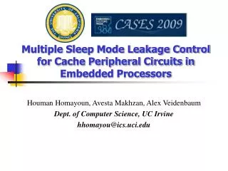
Multiple Sleep Mode Leakage Control for Cache Peripheral Circuits in Embedded Processors. Houman Homayoun, Avesta Makhzan, Alex Veidenbaum Dept. of Computer Science, UC Irvine hhomayou@ics.uci.edu. On-chip Caches and Power . On-chip caches in high-performance processors are large

E N D
Multiple Sleep Mode Leakage Control for Cache Peripheral Circuits in Embedded Processors Houman Homayoun, Avesta Makhzan, Alex Veidenbaum Dept. of Computer Science, UC Irvine hhomayou@ics.uci.edu
On-chip Caches and Power • On-chip caches in high-performance processors are large • more than 60% of chip budget • Dissipate significant portion of power via leakage • Much of it was in the SRAM cells • Many architectural techniques proposed to remedy this • Today, there is also significant leakage in the peripheral circuits of an SRAM (cache) • In part because cell design has been optimized Pentium M processor die photo Courtesy of intel.com • Using minimal sized transistor for area considerations in cells and larger, faster and accordingly more leaky transistors to satisfy timing requirements in peripherals. • Using high vt transistors in cells compared with typical threshold voltage transistors in peripherals
Leakage Power Component of Different Cache Size • SRAM peripheral circuits dissipate more than 80% of the total leakage power
A Zig-Zag Circuit • Rpeq for the first and third inverters and Rneq for the second and fourth inverters doesn’t change. • Fall time of the circuit does not change
A Zig-Zag Share Circuit • To improve leakage reduction and area-efficiency of the zig-zag scheme, using one set of sleep transistors shared between multiple stages of inverters (ICCD’08) • Zig-Zag Horizontal Sharing • Minimize impact on rise time • Minimize area overhead • Zig-Zag Horizontal and Vertical Sharing • Maximize leakage power saving • Minimize the area overhead Increasing the bias voltage increases the leakage power while decreases the wakeup delay overhead
Multiple Sleep Modes • Power overhead of waking up peripheral circuits • Almost equivalent to the switching power of sleep transistors • Sharing a set of sleep transistors horizontally and vertically for multiple stages of a (wordline) driver makes the power overhead even smaller
Low-end Architecture • Given the miss service time of 30 cycles • likely that processor stalls during the miss service period • Occurrence of additional cache misses while one DL1 cache miss is already pending further increases the chance of pipeline stall
100% 90% 80% 70% 60% 50% 40% 30% 20% 10% 0% fft bc gs crc sha pgp gsm mad lame qsort djpeg tiff2bw search dijkstra patricia rijndael average basicmath susan_edges susan_corners hp trivial-lp lp aggr-lp ultra-lp Low Power Modes in a 2KB DL1 Cache • 85% of the time DL1 peripherals put into low power modes • Most of the time spent in the basic-lp mode (58% of total execution time) Fraction of total execution time DL1 cache spends in each of the power mode