Download
1 / 11
110 likes | 119 Vues
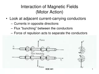
Interaction of Magnetic Fields (Motor Action). Look at adjacent current-carrying conductors Currents in opposite directions Flux “bunching” between the conductors Force of repulsion acts to separate the conductors. Interaction of Magnetic Fields (Motor Action). Currents in the same direction

E N D
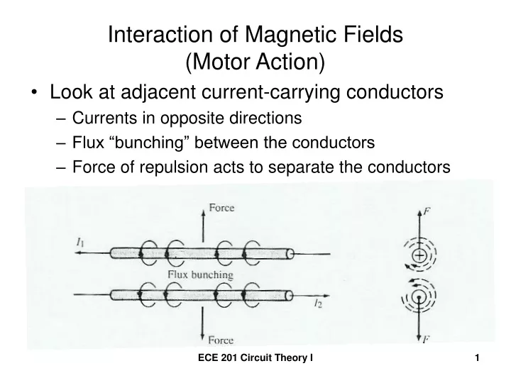
Interaction of Magnetic Fields(Motor Action) • Look at adjacent current-carrying conductors • Currents in opposite directions • Flux “bunching” between the conductors • Force of repulsion acts to separate the conductors ECE 201 Circuit Theory I
Interaction of Magnetic Fields(Motor Action) • Currents in the same direction • Flux in space between conductors in “opposite” directions • Force of attraction acts to pull the conductors together ECE 201 Circuit Theory I
Elementary Two-Pole Motor • Rotor core with 2 insulated conductors in “slots” • A stationary magnet – the “stator” ECE 201 Circuit Theory I
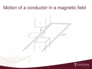
Current-Carrying Conductor in a Magnetic Field • Current-carrying conductor perpendicular to the B-field ECE 201 Circuit Theory I
Magnitude of the force on the conductor in a Magnetic Field • Magnitude of the mechanical force on the conductor is Where F = mechanical force (N) B = flux density in the stator field (T) = the effective length of the rotor conductor I = current in the rotor conductor (A) ECE 201 Circuit Theory I
Conductor “skewed” to the B-fieldby angle = effective length of the rotor conductor (m) leffective ECE 201 Circuit Theory I
Single-Loop Rotor CoilCarrying a CurrentSituated in a Two-Pole Field ECE 201 Circuit Theory I
Torque produced by the 2-conductor couple ECE 201 Circuit Theory I
Elementary Two-Pole Generator ECE 201 Circuit Theory I
Voltage induced in the coil, e • Flux through the coil window is sinusoidal • Φ= Φmaxsin(ωt) • Voltage induced in coil,e • e = N(dΦ/dt) • e = NωΦmaxcos(ωt) • Emax = ωNΦmax • Emax = 2πfNΦmax • Erms = 4.44fNΦmax ECE 201 Circuit Theory I
Directions of induced voltage and current • Develop CCW counter-torque • “Bunching” must occur at the top of coil side B and the bottom of coil side A • Coil current is CCW as viewed from south pole ECE 201 Circuit Theory I