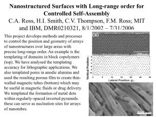
Download
1 / 19
190 likes | 199 Vues
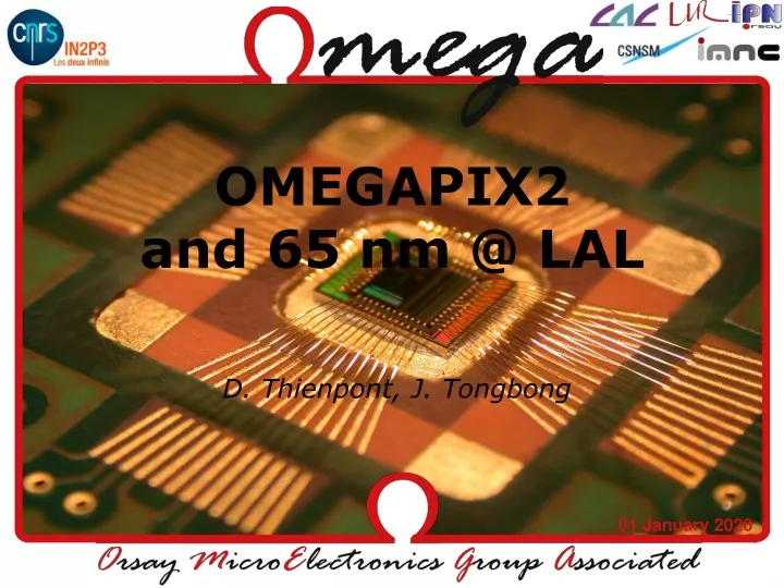
OMEGAPIX2 and 65 nm @ LAL. D. Thienpont, J. Tongbong. OMEGAPIX2 submission. Circuit has been submitted in October 10th via CMP 96 x 24 pixels, 35x200 μ m 2 tiers Analog tier: analog front-end, DACs, BIAS, rad-hard digital cells (Triple Voting)

E N D
OMEGAPIX2and 65 nm @ LAL D. Thienpont, J. Tongbong
OMEGAPIX2 submission • Circuit has been submitted in October 10th via CMP • 96 x 24 pixels, 35x200 μm • 2 tiers • Analog tier: analog front-end, DACs, BIAS, rad-hard digital cells (Triple Voting) • Digital tier: circular memory (6 different flavours, probes), writing and reading independent operations, 60-deep memory (3 μs with 50 ns bunch crossing) • Fully full-custom design
Analog Tier • Targets • Dynamic range: 0 to 40 000 electrons • Low threshold (~ 1000 electrons), low noise (<200 electrons) • Power dissipation: ~ 4 μA • Leakage current compensation: up to 100 nA • Time over threshold (ToT) capability • Preamplifier • Regulated followed cascode NMOS common source • Leakage current compensation based on an OTA circuit in feedback: 0 -> 100 nA • Constant current in feedback to discharge the gain capacitance: ToT purpose • Low noise: < 200 e- with Cd • Detector capacitance: 200 – 300 fF • Second gain stage / Shaper • Regulated followed cascode PMOS common source • Capacitive coupling: parallel noise independent • Gain = ~ 1 • Feedback structure based on an OTA to tune the DC level at the shaper output: 5-bit DAC • Comparator • Classical structure • 3-bit DAC to choose the threshold • Slow Control DFlipFlops • Injection capacitance, 8-bit DAC, External Trigger • Triple Voting, interleaved layout • Layout • 96 rows, 24 columns • Pitch = 35x200 μm • Macropixel = 2 pixels with staggered analog inputs: bump bond pitch = 70 μm • Match with the last sensor submission
Analog Signals • inInj: pin to inject via injection capacitance • Analog_input<96>: injection directly to the 96th pixel • Probe_pa • Probe_sh • Probe_trigger • Srin_sc: Slow Control SR input (2882 Bytes !) • Rstb_sc: Slow Control SR reset (active low) • Clk_sc: Slow Control SR clock • Srout_sc: Slow Control SR output • Srin_ptobe_TA: probe SR input (864 Bytes) • Rstb_probe_TA: probe SR reset (active low) • Clk_probe_TA: probe SR clock • Srout_probe_TA: probe SR output • ExtTrigger: ‘1’ => trigger = Vshaper - Vth; ‘0’ => trigger = ‘1’
Digital tier • Different flavours of circular memory • Typical 15/1 NMOS, LVT 15/1 NMOS, typical 5/1 NMOS, lvt 5/1 NMOS, typical 3p3 NMOS, real capacitance • Analog probes • 60-deep circular memory • Writing operation independent of reading one • 3-bit ToT capability • 3-bit gray counter after L1 • External trigger • Layout: better attention about digital signal propagation than MEMDYN
Digital Signals (1) • Reset_mem (active low): reset of ToT_counter, ToT logic and overlapping logic • Reset_read (active low): reset of read cursors => unselect for reading all memory cells • Rstb (active low): reset of write cursors (select by default the first memory cell), test SR (pixel selection for external trigger), data SR • Rstb_probe_TD (active low): reset of probe SR • Clk_read: clock of read cursors • Clk_write: clock of write cursors • Clk_triggerOK: clock for overlapping detection • Clk_mem: clock for ToT calculation after L1 • Clk_test: clock for test SR (pixel selection for external trigger) • Clk_probe_TD: clock for probe SR • Clk_dataSR: clock for data SR • In_test: external trigger • Load_dataSR: ‘0’ => counter memorizing; ‘1’ => data after L1 shift register
Digital Signals (2) • Srin_test, rstb, clk_test, srout_test: SR to select active pixels for external trigger testing (2304 bits) • Srin_probe_TD, rstb_probe_TD, clk_probe_TD, srout_probe_TD: SR to select which pixel to probe (576 bits) • dataSRin, clk_dataSR, rstb, dataSRout: SR to read out all triggered data (6912 bits) Look out ! ! ! DFF from 3-bit counter are synchronous resetable
65 nm • A new OMEGAPIX chip in 65 nm techno as an alternative to the 3D chip • Same pixel form factor: 35x200 μm • New analog front-end (LAL), new digital pixel (LPNHE) • TSMC 65 nm techno • 3x1z1u metal stack (RF, CRN65LP), 6 metal layers + RDL • tcbn65lp standard cells library • In waiting for the common PDK provided by CERN
65 nm: Analog front-end • A very classical architecture with preamp, shaper and comparator is designing
65 nm: Simulations • Typical Low Power transistor • Cf = 15 fF => 66 mV/fC • with Cd = 300 fF, ENC from 150 e- to 166 e- when leakage current varies from 0 to 100 nA • Preamp Open Loop gain = 90 dB • Global power consumption: vdd = 1.2 V and I = 8 μA => 9.6 μW • Dynamic range: 450 mV max. • 2.5 V transistor • Cf = 15 fF => 66 mV/fC • With Cd = 300 fF, ENC from 128 e- to 150 e- • Preamp Open Loop gain = 90 dB • Global Power consumption: vdd = 2.5 V and I = 8 μA => 20 μW • Dynamic range: 1 V • DAC • Not yet, which resistor can be used ?
Charge Pump PLL • The charge pump PLL is one of the most popular PLL structures since the 80s • Featured with a digital phase detector and a charge pump • Advantages • Fast lock and tracking • No false lock • Fully integrated • Low power and jitter
Charge Pump PLL • PFD : classical architecture with D-flipflop • CP : A NMOS switches Current steering , in order to improve the matching betwen Iup and Idown (I=50uA, Vdd=1,2V) • A 2nd order loop filter : -stability -reduction of jitter at high frequencies Ip VC C1 C2 R
Charge Pump PLL (VCO) Kvco =f(Vctrl) • High gain : Kvco = 1300Mhz/V • N=5 (number of delay cells) • A high Kvco may become an issue for the system stability => Reducing ICP , tradeoff between loop filter parameters, improving the filter order (3rd order, …) PMOS symetrical load delay cell
65nm • MC simulations (another sheet with mac transistors ???) • Use of 2.5 V transistors for analog applications ? • Process deviations with 1.2V transistors when using architectures with mismatches problemns (current mirrors, differential pairs, etc…) • Other blocs implemented (OTAs, amplifier, …)


![Nm]](https://cdn3.slideserve.com/6300766/slide1-dt.jpg)