Download
1 / 36
370 likes | 390 Vues
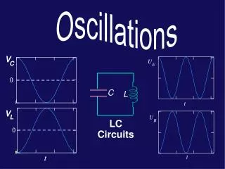
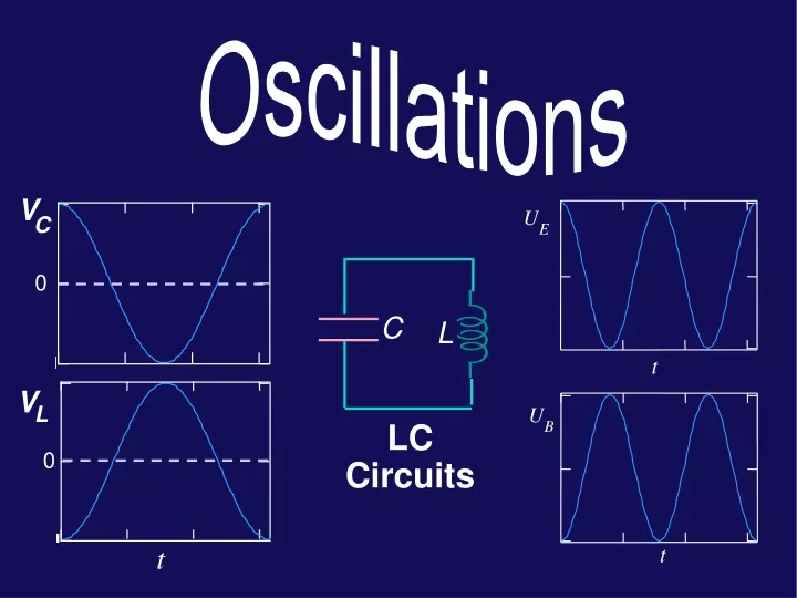
U. E. t. U. B. t. V. C. 0. C. L. V. L. LC Circuits. 0. t. Oscillating voltage and current Transformers Qualitative descriptions: LC circuits (ideal inductor) LC circuits ( L with finite R ) Quantitative descriptions: LC circuits (ideal inductor)

E N D
U E t U B t V C 0 C L V L LC Circuits 0 t
Oscillating voltage and current Transformers Qualitative descriptions: LC circuits (ideal inductor) LC circuits (L with finite R) Quantitative descriptions: LC circuits (ideal inductor) Frequency of oscillations Energy conservation Today...
eosinwt I(t) Oscillating circuits have both AC voltage and current. Simple for resistors, but... Þ ~ ~ eosinwt R Oscillating Current and Voltage Q. What does mean?? A. It is an A.C. voltage source. Output voltage appears at the terminals and is sinusoidal in time with an angular frequency w.
The AC current in the primary circuit creates a time-varying magnetic field in the iron iron ~ V1 e V2 N N 1 2 (secondary) (primary) • AC voltages can be stepped up or stepped down by the use of transformers. Transformers • This induces an emf on the secondary windings due to the mutual inductance of the two sets of coils. • The iron is used to maximize the mutual inductance. We assume that the entire flux produced by each turn of the primary is trapped in the iron. (Recall from magnetism lab how the ferromagnet “sucks in” the B-field.)
The primary circuit is just an AC voltage source in series with an inductor. The change in flux produced in each turn is given by: Nothing connected on secondary No resistance losses All flux contained in iron iron ~ V e V 1 2 N N 1 2 (secondary) (primary) • The change in flux per turn in the secondary coil is the same as the change in flux per turn in the primary coil (ideal case). The induced voltage appearing across the secondary coil is given by: Ideal Transformers (no load) • Therefore, • N2 > N1Þ secondary V2 is larger than primary V1 (step-up) • N1 > N2Þ secondary V2 is smaller than primary V1 (step-down) • Note: “no load” means no current in secondary. The primary current, termed “the magnetizing current” is small!
Power is dissipated only in the load resistor R. iron R V e V ~ 1 2 N N 1 2 (secondary) (primary) = • Changing flux produced by primary coil induces an emf in secondary. When we connect a resistive load to secondary coil, emf in secondary current I2 in secondary Ideal Transformer (with a load) Where did this power come from? It could come only from the voltage source in the primary:
The primary coil of an ideal transformer is connected to an AC voltage source as shown. There are 50 turns in the primary and 200 turns in the secondary. If V1 = 120 V, what is the potential drop across the resistor R ? iron R V e V ~ 1 2 1A 1B N N 1 2 (secondary) (primary) (c)480 V (c)32A (b)120V (b)16A (a)30 V (a)8A Lecture 18, ACT 1 • If 960W are dissipated in the resistor R, what is the current in the primary ?
The primary coil of an ideal transformer is connected to an AC voltage source as shown. There are 50 turns in the primary and 200 turns in the secondary. If V1 = 120 V, what is the potential drop across the resistor R ? iron R V e V ~ 1 2 1A N N 1 2 (secondary) (primary) (c)480V (b)120V (a)30 V Lecture 18, ACT 1 The ratio of turns, (N2/N1) = (200/50) = 4 The ratio of secondary voltage to primary voltage is equal to the ratio of turns, (V2/V1) = (N2/N1) Therefore, V2= 480 V
The primary coil of an ideal transformer is connected to an AC voltage source as shown. There are 50 turns in the primary and200turns in the secondary. If V1 = 120 V, what is the potential drop across the resistor R ? iron R V e V ~ 1 2 1B 1A N N 1 2 (secondary) (primary) (c)480V (c)32A (b)120V (b)16A (a)30 V (a)8A Lecture 18, ACT 1 The ratio of turns, (N2/N1) = (200/50) = 4 The ratio (V2/V1) = (N2/N1). Therefore, V2= 480 V • If 960 W are dissipated in the resistor R, what is the current in the primary ? Energy is conserved—960W should be produced in the primary P1 = V1I1 implies that 960W / 120V = 8 A
Preflight 18: An ideal transformer has N1 = 4, N2 = 6. Side 1 is connected to a generator with e = Vmax sin ( w t ) 2) What is the maximum EMF on side 2? a) V2max = 2e1/3 b) V2max = e1 c) V2max = 3e1/2 1 2
An ideal transformer steps down the voltage in the secondary circuit. The number of loops on each side is unknown. 4) Compare the currents in the primary and secondary circuits • I1 < I2 • I1 = I2 • I1 > I2
Why and how do oscillations occur in circuits containing capacitors and inductors? naturally occurring, not driven for now stored energy capacitive <-> inductive Where are we going? • Oscillating circuits • radio, TV, cell phone, ultrasound, clocks, computers, GPS What’s Next?
Energy in the Electricand Magnetic Fields Energy stored in a capacitor ... E +++ +++ - - - - - - … energy density ... B Energy stored in an inductor …. … energy density ...
Consider from point of view of energy! In the RC circuit, any current developed will cause energy to be dissipated in the resistor. In the LC circuit, there is NO mechanism for energy dissipation; energy can be stored both in the capacitor and the inductor! ++++ - - - - ++++ - - - - C C R L LC Circuits • Consider the RC and LC series circuits shown: • Suppose that the circuits are formed at t=0 with the capacitor charged to value Q. There is a qualitative difference in the time development of the currents produced in these two cases. Why??
I I Q +++ Q C L +++ - - - C R - - - LC: current oscillates RC: current decays exponentially I I 0 0 0 0 t t RC/LC Circuits
+ + C C L L - - - - C C L L + + LC Oscillations(qualitative) Þ ß Ý Ü
C VC = Q/C V=0 VL = L dI/dt L VC+VL= 0 VC= -VL Alternate way to draw:
Q 0 V C 0 I 0 V L 0 t t LC Oscillations(qualitative) These voltages are opposite, since the cap and ind are traversed in “opposite” directions dI dt 0
Att=0, the capacitor in the LCcircuit shown has a total charge Q0. At t = t1, the capacitor is uncharged. What is the value of Vab=Vb-Va, the voltage across the inductor at timet1? t=t t=0 1 a + + = = Q 0 L L Q Q 0 - - C C 2A b (c)Vab> 0 (b)Vab = 0 (a)Vab < 0 • What is the relation between UL1, the energy stored in the inductor at t=t1, and UC1, the energy stored in the capacitor at t=t1? 2B (c) UL1 > UC1 (b)UL1 = UC1 (a)UL1 < UC1 Lecture 18, Act 2
Att=0, the capacitor in the LC circuit shown has a total charge Q0. At t = t1, the capacitor is uncharged. What is the value of Vab=Vb-Va, the voltage across the inductor at timet1? t=t t=0 1 a + + = = Q 0 L L Q Q 0 - - C C 2A b (c)Vab> 0 (b)Vab = 0 (a)Vab < 0 Lecture 18, Act 2 • Vab is the voltage across the inductor, but it is also (minus) the voltage across the capacitor! • Since the charge on the capacitor is zero, the voltage across the capacitor is zero!
Att=0, the capacitor in the LC circuit shown has a total charge Q0. At t = t1, the capacitor is uncharged. t=t t=0 1 a + + L L = = Q 0 Q Q - 0 - C C 2B b • At t=t1, the charge on the capacitor is zero. • At t=t1, the current is a maximum. (c) UL1 > UC1 (b)UL1 = UC1 (a)UL1 < UC1 Lecture 18, Act 2 • What is the relation between UL1, the energy stored in the inductor at t=t1, and UC1,the energy stored in the capacitor at t=t1?
Preflight 18: At time t = 0 the capacitor is fully charged with Qmax, and the current through the circuit is 0. 2) What is the potential difference across the inductor at t = 0? a) VL = 0 b) VL = Qmax/C c) VL = Qmax/2C 3) What is the potential difference across the inductor when the current is maximum? a) VL = 0 b) VL = Qmax/C c) VL = Qmax/2C
If L has finite R, then energy will be dissipated in R the oscillations will be damped. Q Q 0 0 t t LC Oscillations(L with finite R) R¹ 0 R = 0 • The number of oscillations is described by the “Q” of the oscillator (we will return to this in Lect. 20) [NOTE: Q here is not charge!] Umaxis max energy stored in the system DU is the energy dissipated in one cycle
I(t) C I(t) Voltage determined by derivative of current and inductance L Review of Voltage DropsAcross Circuit Elements Voltage determined by integral of current and capacitance
where f,Q0determined from initial conditions I + + Q C L - - remember: LC Oscillations(quantitative, but only for R=0) • What is the oscillation frequency ω0? • Begin with the looprule: • Guess solution:(just harmonic oscillator!) • Procedure: differentiate above form for Q and substitute into loop equation to findw0. • Note: Dimensional analysis
General solution: + + C L - - • Differentiate: • Substitute into loop eqn: Þ Therefore, which we could have determined from the mass on a spring result: LC Oscillations(quantitative)
At t=0 the capacitor has charge Q0; the resulting oscillations have frequency w0. The maximum current in the circuit during these oscillations has value I0. What is the relation between w0and w2, the frequency of oscillations when the initial charge =2Q0? 3A (c) w2 = 2w0 (b)w2 = w0 (a) w2 = 1/2 w0 • What is the relation between I0and I2,the maximum current in the circuit when the initial charge =2Q0? 3B (c)I2 = 4I0 (b)I2 = 2I0 (a)I2 = I0 Lecture 18, Act 3
At t=0 the capacitor has charge Q0; the resultingoscillations have frequency w0. The maximum current in the circuit during these oscillations has value I0. What is the relation betweenw0and w2, the frequency of oscillations when the initial charge = 2Q0? 3A (c) w2 = 2w0 (b)w2 = w0 (a)w2 = 1/2 w0 Lecture 18, Act 3 • Q0 determines the amplitude of the oscillations (initial condition) • The frequency of the oscillations is determined by the circuit parameters(L, C),just as the frequency of oscillations of a mass on a spring was determined by the physical parameters(k, m)!
At t=0 the capacitor has charge Q0; the resultingoscillations have frequency w0. The maximum current in the circuit during these oscillations has value I0. What is the relation betweenI0 and I2, the maximum current in the circuit when the initial charge = 2Q0? 3B (c)I2 = 4I0 (b)I2 = 2I0 (a)I2 = I0 Lecture 18, Act 3 • The initial charge determines the total energy in the circuit: • U0 = Q02/2C • The maximum current occurs whenQ=0! • At this time, all the energy is in the inductor:U = 1/2 LIo2 • Therefore, doubling the initial charge quadruples the total • energy. • To quadruple the total energy, the max current must double!
Preflight 18: The current in a LC circuit is a sinusoidal oscillation, with frequency ω. 5) If the inductance of the circuit is increased, what will happen to the frequency ω? a) increase b) decrease c) doesn’t change 6) If the capacitance of the circuit is increased, what will happen to the frequency? a) increase b) decrease c) doesn’t change
The other unknowns(Q0,f)are found from the initial conditions. E.g., in our original example we assumed initial values for the charge(Qi)and current(0). For these values: Q0 = Qi,f = 0. • Oscillation frequency has been found from the loop equation. LC OscillationsEnergy Check • Question: Does this solution conserve energy?
Energy in Capacitor Energy in Inductor 0 t Þ U B Therefore, 0 t 4 Energy Check U E
Att=0the current flowing through the circuit is 1/2 of its maximum value. Which of the following plots best representsUB,the energy stored in the inductor as a function of time? I + + Q C L - - 4 (c) (b) (a) UB UB UB 0 0 0 0 0 0 time time time Lecture 18, Act 4
Att=0 the current flowing through the circuit is 1/2of its maximum value. Which of the following plots best representsUB, the energy stored in the inductor as a function of time? I + + Q C L - - 4 (c) (b) (a) UB UB UB 0 0 0 0 0 0 time time time Lecture 18, Act 4 • The key here is to realize that the energy stored in the inductor is proportional to the CURRENT SQUARED. • Therefore, if the current at t=0 is 1/2 its maximum value, the energy stored in the inductor will be 1/4 of its maximum value!!
Quantitative description Frequency of oscillations Energy conservation V C 0 V L 0 • Transformers used to step up/down voltage Summary • Oscillating voltage and current • Qualitative description
Appendix: LCR DampingFor your interest, we do not derive here, but only illustrate the following behavior Q + + C L - - 0 t In an LRC circuit, w depends also on R ! Q 0 t