Download
1 / 13
130 likes | 258 Vues
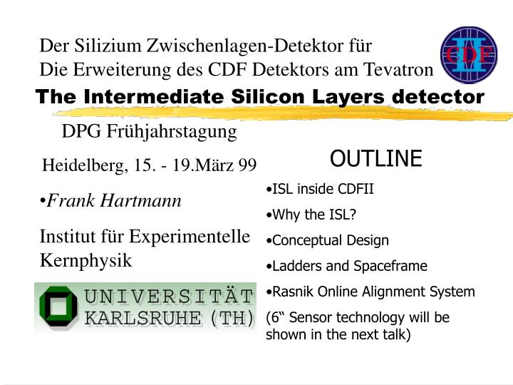
Der Silizium Zwischenlagen-Detektor für Die Erweiterung des CDF Detektors am Tevatron. The Intermediate Silicon Layers detector. DPG Frühjahrstagung Heidelberg, 15. - 19.März 99 Frank Hartmann Institut für Experimentelle Kernphysik. OUTLINE ISL inside CDFII Why the ISL?

E N D
Der Silizium Zwischenlagen-Detektor für Die Erweiterung des CDF Detektors am Tevatron The Intermediate Silicon Layers detector • DPG Frühjahrstagung • Heidelberg, 15. - 19.März 99 • Frank Hartmann • Institut für Experimentelle Kernphysik • OUTLINE • ISL inside CDFII • Why the ISL? • Conceptual Design • Ladders and Spaceframe • Rasnik Online Alignment System • (6“ Sensor technology will be shown in the next talk)
THE CDF II DETECTOR & THE ISL The ISL
SVXII (Silicon Vertex) + Layer00 • 3 barrels 5 layers • 12 wedges • Radii 2.45 - 10.6 cm • layer 0,1,3 90o • layer 2,4 + 1.2o Layer00 Beyond baseline Radius 1.6 cm
COT Why the ISL? • High momentum resolution combined with COT |h|<1 • Fine granularity helps to resolve ambiguities in dense track environments (e.g. in stiff jets t t ) • ISL & SVXII combined provide a precision standalone silicon tracking system with up to 7 axial and 7 stereo measurements • Adds forward tracking (1<|h|<2) • pT resolution: • impact parameter: • Add. Spacepoint --- R=10.6 and 40 cm ISL SVXII Distribution of primary vertices (z)
ISL Conceptual Design Considerations • Simple design, limited R&D • Take advantage of SVXII R&D • use the same electronics and DAQ. • Take advantage of the large radial position of the layers • less radiation ==> S/N can be lower ==> more surface area of Silicon per readout channel. • hit density is much lower ==> larger strip pitch and relaxed mechanical tolerances. • Material: 0.5% rad. length (central region) • 1% rad. length (forward region) • 1% rad. Length (hybrids, endcaps, cooling) ?
ISL System Components • ~ 888 large area, double sided silicon microstrip sensors. • 303 104 total channels • 512 strips on each side with a pitch of 112mm • Strips on one side have a stereo angle of 1.2 degrees • Sensors grouped into readout triplets called ladders • Each ladder has double-sided AlN readout hybrid. • Sensors and hybrid are supported by a carbon fiber shell. • 296 Ladders are paired to form 148 modules. • Modules installed on Carbon fiber supports to form barrels. • ISL Barrels are assembled into a space frame • Operational temperature 10-150C ; water cooling (chilled water) ISL 3 * 900 layers 4 * 1.20 layers
Mechanical design of the spaceframe • RINGS: Carbon fiber • RODS: Hollow carbon fiber • No direct connection to carbon fiber ladders, only to hybrids • FEA: gravitational sag 20mu • Weight 7 kg Radii: ~20cm & ~30cm 195,2 cm Every second ladder displayed
Spaceframe: Al Prototype Forward Barrel Spaceframe Assembly mechanical ladder dummies Expected final precision 50mu overall Final carbon fiber rods (hollow)
ISL Ladder Design and Mounting (1) • max rigidity & min material due to carbon fiber design • Full rigidity reached with sensor gluing • Geometry allows easy microbonding Wedge shape to max rigidity
ISL Ladder Design and Mounting (2) Hybrid tower (rotating) with precision pin 3 silicon sensor tower with teflon (x,y,rotating) Position precision dependent on silicon only, alignment hole on hybrid High precision bearings z-stages Al support for the carbon ladder • Ladder will be placed on Al support beneath the teflon planes. • Silicon sensors will be positioned in respect to the hybrid‘ precision hole. • Glue will be put on carbon fiber ladder. • Support and ladder will be elevated to connect ladder and silicons.
Rasnik: The Online Alignment System (1) shields IR shields • Coded Masks - Lenses - CCDs • Movement of one part induces a • shift in the mask-image in the CCD. • Online Alignment check • Submicron range CCD image of the mask
Rasnik: The Online Alignment System (2) • Cheap alignment system • Simply controlled and readout with one PC
Conclusion • The ISL is a relatively young project (starting OCT. 96) • ISL/SVXII allows standalone tracking • Most Spaceframe parts are ready and partially mounted • Mounting fixtures are ready • MICRON as well as HAMAMATSU are delivering silicon sensors • Hybrids are in production • First prototype ladder has been built and is working • Preproduction will start next month • Engineering RUN spring 2000; DATA TAKING fall 2000