Download
1 / 17
170 likes | 364 Vues
Simulation of electric field profile in Si irradiated detectors with a consideration of carrier generation parameters. E. Verbitskaya , V. Eremin Ioffe Physical-Technical Institute of Russian Academy of Sciences St. Petersburg, Russia. 21 RD50 Collaboration Workshop

E N D
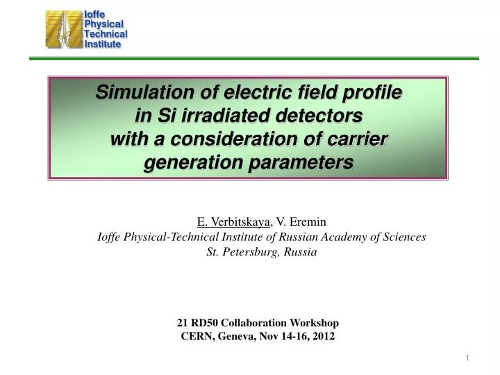
Simulation of electric field profile in Si irradiated detectors with a consideration of carrier generation parameters E. Verbitskaya, V. Eremin Ioffe Physical-Technical Institute of Russian Academy of Sciences St. Petersburg, Russia 21 RD50 Collaboration Workshop CERN, Geneva, Nov 14-16, 2012
Outline ♦ Goals ♦ Model of E(x) profile in Si heavily irradiated detectors developed in PTI ♦ Alternative methods of simulation ♦ Comments on lifetime ♦ Results on I, tgen, Neffand E(x) based on PTI approach ♦ Impact of bulk generation on E(x) profile Conclusions E. Verbitskaya, V. Eremin, 21 RD50 workshop, Nov 14-16, 2012, CERN
Goals Goals: Analysis of the impact of carrier generation (bulk generation current) on the electric field profile in Si irradiated detectors Finding the correct approach for E(x) simulation Importance: Correct E(x) is required for adequate calculation of CCE Earlier/Related results: Temperature dependences of reverse current: activation energy of generation current of 1 MeV neutron and 23 GeV proton irradiated detectors was estimated as 0.65 eV (E. Verbitskaya, et al., 20 RD50 workshop) Recent results on I(T) scaling: simulation and experiment; A. Chilingarov, RD50 notes and presentation at 18 RD50 workshop, May 2011, Liverpool Presentations in Bari on electric field simulation E. Verbitskaya, V. Eremin, 21 RD50 workshop, Nov 14-16, 2012, CERN
Global result of RD50 collaboration DI/Vol = aFeq a = 3.7x10⁻¹⁷ A/cm Linear fit of I(F) is a strong argument to use linear dependence of the concentration of energy levels, which act as generation centers, on Feq G. Lindström, NIM A 512 (2003) 30 E. Verbitskaya, V. Eremin, 21 RD50 workshop, Nov 14-16, 2012, CERN
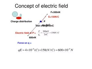
je(x) jh(x) p+ n+ Neff p+ n+ E(x) p+ n+ Approach for calculation of E(x) profile (PTI model) • We consider two independent processes which control E(x) profile • Equilibrium carrier generation • (bulk generation current, tgen): • Ibgen = eniVol/tgen • Generation occurs in SCR via effective generation level (0.65 eV), • introduction rate Mj = 1 cm-1, • se = sh = 1x10-13 cm2, s(T) = so(T/To)-2 • (defined from our I(T) data) • divJgen = G; G = ni/tg • G – generation rate • jgen ~ Gxdepth • Electron and hole components • je(x)= Gx; jh(x)= G(d – x) • This level does not contribute to Neff At F > FSCSI E. Verbitskaya, V. Eremin, 21 RD50 workshop, Nov 14-16, 2012, CERN
Approach for calculation of E(x) profile 2. Trapping to deep levels DDs: Ev + 0.48 eV; DAs: Ec – (0.5250.005) eV – midgap levels used in all PTI simulations and fits Filling factors are calculated for DDs and DAs which charged fractions contribute to Neff No contribution of DDs and DAs to generation current! Then Poisson equation: dE/dx = -eNeff/eeo → E(x) Method: Numerical simulation (EXCEL) p-on-n Double Peak (DP) E(x) profile E. Verbitskaya, V. Eremin, 21 RD50 workshop, Nov 14-16, 2012, CERN
Alternative issues: comments Recently: Simulation of detector characteristic using standard simulating software (ISE-TCAD, Atlas (Silvaco), etc.) Pres. at 20 RD50 workshop, Bari: R. Eber, Karsruhe, KIT; M. Miñano, IFIC, Valencia; also results from Deli University group Main features DDs and DAs are implemented (the same levels as in PTI model) which are considered as traps and generation levels Disagreement in current when calculating with standard simulator, no DP E(x) To agree with expected current calculated from a and F, tuning of initial parameters is done (suggested: cross-sections, reduced lifetime, introduction rate) Question: lifetime – is it recombination lifetime as in Simulator Standard physics model for a sensor with no radiation damage? Value? E. Verbitskaya, V. Eremin, 21 RD50 workshop, Nov 14-16, 2012, CERN
main junction Base, diffusion SCR, generation -V Jdr e Jdr h p+ n+ Alternative issues: comments At F beyond SCSI → p-Si in base region, electrons are minor carriers which diffuse towards SCR If recombination is considered: Idif depends on Ldif = (Dtrec)0.5 to (d-W) ratio In SCR DivJdr e,h = 0 Je_dr = enve_dr = Je_dif = const If so, no DP E(x) arises! Also, generation and diffusion have different dependences on V and T Igen(V) ~ V0.5 (w ~ V0.5)Igen(T) ~ exp(-Eg/2kT) - plot I-V in log-log scale Idif (V) = Is at V > 2kT/eIdif(T) ~ exp(-Eg/kT) This may be the most probable reason for necessity to make tuning/tailoring/ /adjustment of initial parameters for simulation (e.g., s, K) in standard software (see presentations on Simulation mentioned above and at 21 RD50 workshop) E. Verbitskaya, V. Eremin, 21 RD50 workshop, Nov 14-16, 2012, CERN
Relationship between different lifetimes Generation-recombination currents are described by Sah-Noyce-Shockley model When pn<ni2, generation rate U: S. M. Sze. Physics of Semiconductor Devices Generation: If n=p=ni tgen_min 2trec Trapping – controls CCE; all levels contribute to t since pulse signal is measured within q = 25 ns that is far less than detrapping time constant for larger energy gap (at RT) Uncertainty in lifetime may be the most probable reason for necessity to make tuning/tailoring/adjustment of initial parameters for simulation in standard software (see presentations on Simulation mentioned above and at 21 RD50 workshop) E. Verbitskaya, V. Eremin, 21 RD50 workshop, Nov 14-16, 2012, CERN
Generation lifetime vs. F Ibgen = eniVol/tgen; Ibgen = aFVol For trapping: 1/ttr = bFeq be = 3.2x10⁻¹⁶ cm2ns-1; be = 3.5x10⁻¹⁶ cm2ns-1 tgen = (eni /a)F-1 ttr_e = 3.1x10⁶/Feq ttr_h = 2.9x10⁶/Feq I. Mandić, et al., NIM A 612 2010) 474 tgen = 4.32x10⁷/Feq tgen 15ttr For Feq = 1x1014 cm-2 tgen = 4.3x10⁻⁷ s whereas lifetime used in Silvaco t ≈ 1x10⁻⁷ s – recombination lifetime? How to insert t(F) in standard software? E. Verbitskaya, V. Eremin, 21 RD50 workshop, Nov 14-16, 2012, CERN
Another trend in alternative issues: implementation of multiple traps In plots: concentration of charged DLs and total Neff Feq ~ 1014 cm-2 DLs: DD, DA, VV- NVV = 1x1014 cm-3 NVV = 1x1016 cm-3 NVV = 1x1017 cm-3 DLs with Ea ~ 0.4 eV affect: ♦ space charge region depth (at very high F); ♦ trapping time constant Deep levels with Ea ~ 0.4 eV (VV, Ci-Oi) hardly affect current E. Verbitskaya, V. Eremin, 21 RD50 workshop, Nov 14-16, 2012, CERN
Reverse current simulation using PTI model Carrier generation via single effective level 0.65 eV Ngen vs. fluence dependence RD50 parameterization: a = 3.7x10⁻¹⁷ A/cm PTI model gives a = 4x10-17 A/cm Linear dependence of Ngen vs. F agrees with data on I(F) No adjustment of parameters Is required E. Verbitskaya, V. Eremin, 21 RD50 workshop, Nov 14-16, 2012, CERN
Results on simulated Neff(x) and E(x) E. Verbitskaya, V. Eremin, 21 RD50 workshop, Nov 14-16, 2012, CERN
Simulation of Igen using two levels E. Verbitskaya, et al., presented at 20 RD50 workshop, Bari, May 30 – June 1, 2012 Bulk generation current may be simulated using two levels (TL): – two independent processes DDs: Ev + 0.48 eV; DAs: Ec – (0.5250.005) eV NDA/NDD = 1.2; kDD = 1 • kDD and kDAare different for • neutrons and 23 GeV protons; • cross-sections should be tuned → Using a single generation level for Igencalculation is more simple and unambiguous E. Verbitskaya, V. Eremin, 21 RD50 workshop, Nov 14-16, 2012, CERN
Impact of Ibgen on E(x) profile Key parameters for adequate E(x) description: bulk generation current and deep traps Impact of Igen – double peak E(x) Simulation without current – no DP E(x) Igen is important parameter since it gives correct E(x) reference to other characteristics (CCE, tdr) E. Verbitskaya, V. Eremin, 21 RD50 workshop, Nov 14-16, 2012, CERN
Conclusions • PTI model considers E(x) profile formation in irradiated Si detectors caused by two independent processes: carrier generation via effective level with Ea = 0.65 eV and carrier trapping to midgap DDs and DAs. • This model gives nice agreement of the current with I(F) dependence Therefore, • Consideration on contribution of bulk generation current gives adequate description of irradiated detector characteristics • The nature of lifetime used in standard simulation software should be clarified E. Verbitskaya, V. Eremin, 21 RD50 workshop, Nov 14-16, 2012, CERN
Acknowledgments • This work was made in the framework of RD50 collaboration • and supported in part by: • Fundamental Program of Russian Academy of Sciences • on collaboration with CERN, • RF President Grant # SS-3008.2012.2 Thank you for attention! E. Verbitskaya, V. Eremin, 21 RD50 workshop, Nov 14-16, 2012, CERN