Download
1 / 33
340 likes | 473 Vues
NSLS – II PAC Review. Conventional Facilities Marty Fallier Director for Conventional Facilities National Synchrotron Light Source – II Project October 27, 2006. Outline. Scope of Conventional Facilities WBS Program Site Plan Buildings Utilities CF Organization

E N D
NSLS – II PAC Review Conventional Facilities Marty Fallier Director for Conventional Facilities National Synchrotron Light Source – II Project October 27, 2006
Outline • Scope of Conventional Facilities • WBS • Program • Site Plan • Buildings • Utilities • CF Organization • Method of Accomplishment • CF Procurement • CF Schedule • CF Cost Estimate • CF Risk Assessment
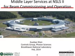
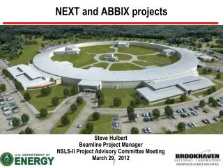
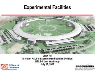
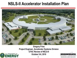
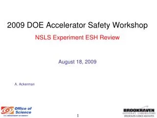
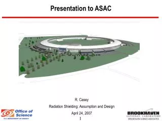
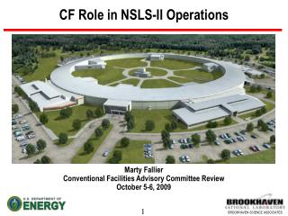
NSLS II Site Plan NSLS Conf. Center Service Bldg Typ 4 CLOB CFN Future JPsi RF-LINAC AREA Future Guest House Ring Bldg LOB Typ 4 Underpass Loading
Ring Building Concept • Divided into 5 clusters • Service Bldg supports all services within the cluster • Six sectors/Cluster • CLOB & Service Bldgs contain all Accelerator systems • Ring, CLOB, LOB 1 & service bldgs are base scope • LOB’s 2,3,4 can be added as needed w/o interruption
Tunnel Design • Roof and wall thicknesses generally driven by shielding criteria except inner wall in area of berm (just structural) • Outer wall (ratchet wall) is HD concrete • During T-I will study whether precast or poured in place provides best balance of technical and cost performance • Tunnel floor thickness driven primarily by vibration criteria • Will do modeling to arrive at optimal thickness and section shape • Rigidly connected to exp. floor to create monolithic floor • Penetrations from above for power and cooling water • Penetrations from sidewall for HVAC Supply and Return
Tunnel Access • Egress for life safety achieved by exits at each service building location • Large shielded doors for equipment access provided at Service buildings for tunnel entry • Personnel doors and labyrinth provided at each Service building • Vehicle ramp to roll-up door at 2nd floor of each Service Bldg provides equipment access to electrical mezzanine at top of tunnel • RF & LINAC areas integrated with CLOB structure have similar access as Service Bldgs
CLOB Features • Space for 190 Offices, 8 labs • Nominally 30 User Offices, 5 User labs from the total • Possible 400 seat Conference Center addition w/ vendor area and three breakout rooms • Lobby and User Reception area • 2nd floor viewing gallery overlooking experimental floor • Bridge to electrical mezzanine and control room & RF/LINAC areas • Close Proximity to future: • JPSI Building • Guest house
LOB Features • Modular design – can be added when needed without interrupting operation • 11,000 SF each – Serves six sectors • 30 offices w/ conference space, interaction areas, lavs, showers • 5 labs intended for shared use • Shipping/Receiving/Storage area & chemical storage area • Potential for expansion for more offices if needed • Egress provided for personnel and large items at each LOB • Loading area with exterior roll-up door • Roll-up door from each lab onto the experimental floor • Designed to minimize impacts to future long beamlines
Utility Support to Buildings • Utilities run underground in center of ring and distributed to five service bldgs (one in CLOB RF/LINAC area) • Minimizes pipe runs and pipe size in bldg proper • Minimizes potential noise and vibration impacts • Mechanical Utilities include: • Chilled water from expansion of Central CHW Plant • Tower water from process cooling water tower • Steam & condensate from Central Steam System • Potable water, compressed air, sanitary to existing mains • Electrical Utilities distributed via substation and load center at each Service bldg • Communication/Data via underground BNL F/O network
Utility Support for Beamlines • Services provided at each Beamline include: • Electric Power Panel at Ratchet Wall, 75-95kW/Cell, 120/208V • Cooling Water Supply and Return • HVAC Supply Air, Central Exhaust • Compressed Air, LN2, GN2 • DI Cooling Water (Copper and Aluminum systems) by Accelerator Group
Conventional Facilities Organization Director Conventional Facilities Marty Fallier Conventional Facilities Deputy Director TBD Construction Manager Agent CM – TBD [C] Conventional Facilities Engineering Staff & WBS Managers Commissioning Contractor TBD [C] Plant Engineering ECS Support Team J. Mills [M] Design A/E T-I, I, III TBD [C] PE Project Architect T. McEvaddy [M] CF Project Architect TBD Design A/E Subconsultants [C] Site Prep Contractor [C] PE Civil/Struct. Engr. T. Joos [M] CF Civil/Struct. Engr. TBD Precast Contractor [C] PE Sr Mech. Engineer C. Channing [M] PE Mech. Engineer G. Leskody [M] CF Mech. Engineer TBD Ring Bldg Contractor [C] [M] – Matrixed [C] - Contracted PE Trade Shop Support – Various [M] PE Elect. Engineer D. Danseglio [M] CF Elect. Engineer TBD CHW Contractor [C]
Design Activities • CF design will be by competitively selected A/E • A/E selection underway – contract ready for award prior to CD-1 • Will perform T-I & II with option for T-III support • Responsible for design of all bldgs and utilities • Must design to cost & provide construction estimates • Design for LEED certification • PE Engineering & Construction Services will provide design & utility coordination support • Provide interface for existing utility systems • Provide QA review and verification of compliance with BNL stds • Coordinate BNL trade craft support during design and construction
Design Activities cont’d • Construction Manager will be competitively selected • Contract award planned for early in T-I • Will be an agent CM contract • Provide constructability review, independent estimate, value engineering and market analysis support during T-I & II design • Commissioning agent will be competitively selected • Contract award during T-I • Provide HVAC and I&C design review • Prepare Cx plan
Construction Packages • Pre-cast shield-wall early procurement – during T-II • Enables reduction in Ring bldg construction duration • Potential for better QA on shieldwall – uniform density • Need to verify cost and structural tradeoffs are acceptablre during T-I • Site Preparation early procurement – during T-II • Enables reduction in Ring bldg construction duration • Reduces risk associated with existing site conditions • Provides more time to deal with unforeseen earthwork issues • Provides longer settlement & compaction time
Construction Packages cont’d • Ring Bldg/CLOB/LOB contract • Work will be phased to support accelerator installation schedule • Package will be as self contained as possible • Should include CHW piping, process water clg tower & LN2 system • Chilled Water Plant Expansion • Expansion contract shared with Lab • 3 chillers for NSLS II, 1 for BNL • Integrated Control & Communication • Could be performed by tech group or ctrls contractor • Standard Equipment • Several OFE items & furnish and install contracts
Construction Management • NSLS II WBS Managers responsible for performance • CM will provide field inspection and coordination services • Oversight of contractor performance of contract • QA, Construction safety, testing, schedule, RFI’s, CO’s, Invoice review • A/E will provide home office support • Engineer of record, shop dwg review, ECN’s, periodic inspection, RFI’s • PE Engineering and construction Services and Trade crafts • Utility interconnect support, shutdowns, start-ups, permits • Cx contractor - checkout and startup of systems • Document test results & performance, training & documentation for operating staff, info for LEED certification
ESH Management • CF has the following responsibilities for ESH during the project: • Design to applicable codes and include engineered safety features to mitigate hazards identified in PHA • Coordinate review and input to design by ESH SME’s • Comply with environmental regulations and stay within operating envelope of the NEPA review (EA) and FONSI • Incorporate sustainable design features and maximize sustainability within budget and operational limits (LEED Certification & possible LEED silver rating) • Select contractors that have above average construction safety performance • Implement an effective construction safety program with 0 injury goal • Test and document all systems to verify safe and efficient performance
CF Procurement • CF scope will primarily be executed by procurement contracts • NSLS II has dedicated procurement staff developing detailed procurement plans for CF contracts • Early planning will provide added assurance that procurement will not create unforeseen delays to schedule • A/E and C/M contracts will be by traditional A/E procurement process called for in FAR and DEAR • Large construction contracts will be evaluated “best value” procurements that take into account technical qualifications as well as cost • Key criteria include safety performance in addition to technical experience, past performance and other weighted factors
CF Procurement Cont’d Major CF Contracts • Design Phase • A/E for Title I, II and option for T-III design • Construction Manager • Commissioning Contractor • CD-3A • Site Preparation contract • HD Shield Wall Pre-cast contract • CD-3B • Ring/CLOB/LOB Building Contract • Chilled Water Plant Expansion Contract • Standard Equipment
Schedule • Key schedule objective – Enable start of accelerator installation June 2010 • CF is critical path until the main bldg spaces are turned over for accelerator installation • Cluster areas of Ring bldg to be released for BO in phases • Key durations: • Title I Design – 9 months • Title II Design – 11 months • Site preparation – 6 months • Main bldg contract bid & award – 6 months • Main bldg contract duration 34 months
Schedule FY07 FY08 FY09 FY010 FY11 FY12 Activity FY13 Title I Design CD-2 Title II Design CD-3 Site Preparation Const. Pre-cast Shield Wall Const. Ring Bldg/CLOB/LOB Bid & Award Construction 1st Cluster ready for Accel. installation Ring Bldg BO CHW Plant Expansion Mech & Elect Utilities Integrated Ctrl & Comm. Standard Equipment Commissioning
CF Risk Assessment • Technical Challenges • Constructing massive concrete tunnel with reasonable economy • Achieving structural stability • Minimizing vibration & differential settlement • Achieving thermal stability – • Tight temperature constraints for tunnel • Assuring interior/exterior thermal gradients don’t affect beam • Making tunnel available for accelerator installation in phases • Risks • Cost & schedule sensitivity of achieving all of the above • Volatile material/construction markets • Detailed risk registry for CF will be prepared for final CDR