Download
1 / 20
270 likes | 908 Vues
Digital FM Demodulator. m.Khafaji. Outline. Introduction to FM Modulation FM signal demodulation Quadrature-Mixer Digital Limiter Baseband Delay Demodulator Phase-Adapter Demodulator Direct Digital Synthesizers. Introduction to FM Modulation.

E N D
Digital FM Demodulator m.Khafaji May 2005
Outline • Introduction to FM Modulation • FM signal demodulation • Quadrature-Mixer • Digital Limiter • Baseband Delay Demodulator • Phase-Adapter Demodulator • Direct Digital Synthesizers
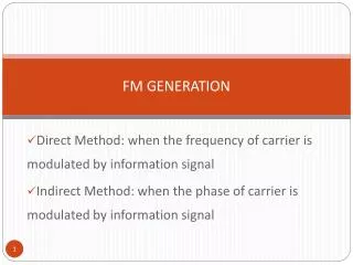
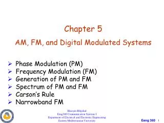
Introduction to FM Modulation • Information signal encoded in carrier frequency (or phase) • Modulated signal is s(t)=Accos(q(t)) q(t)=2pfct+2pkfm(t)dt • Benefits: • Instantaneous frequency: fi=fc+kfm(t) • Signal robust to amplitude variations • Robust to signal reflections and refractions
B2Df WBFM B2Bm NBFM .5AcJn(b) … … Ac .5Acb .5AcJn(b) f fc -4fm fc+fm fc -3fm fc+3fm fc fc -2fm fc+2fm fc+ 4fm fc-fm -.5Acb Spectral Analysis of FM • s(t)=Accos(2pfct+2pkf m(t)dt) • Very hard to analyze for general m(t). • Let m(t)=cos(2pfmt): Bandwidth fm • Using Fourier Series analysis: • Df <<fm b<<1Jn(b)0 for n>1 B 2fm=2Bm • If Df >>fm, significant components up to fc±Df.
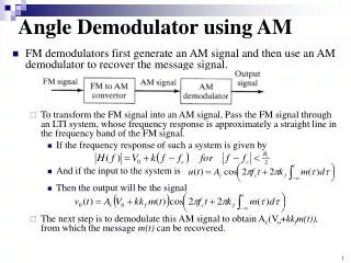
FM signal demodulation • filtering and Limiting the transmitted signal. • Differentiation to obtain the phase information in the modulated signal. • There are four ways to implement differentiation: • Differentiator and Envelope Detector • Zero Crossing Detector • Uses rate of zero crossings to estimate fi • Phase Lock Loop (PLL) • Uses VCO and feedback to extract m(t) • Phase-Shift or Quadrature Detection
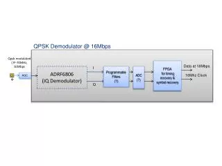
Quadrature-Mixer • The mixing to the baseband is carried out by the multiplication of the FM signal and a complex oscillator ejwTn and a low pass filter • The input signal is: • SFM(n) = A . cos (wTn +FFM (n)) • And the output signal of the mixer is: • Sbasis(n) = • = A/2 . cos (FFM (n)) + jA/2 . sin (FFM (n))
Real quadrature-mixer The mixer can also be realized with real signals by multiplying the FM signal with a sine and cosine oscillation signal Sreal(n) = A/2 . cos (FFM(n)) Simag(n)= A/2 . sin (FFM(n))
Digital Limiter • The received FM signal due to distortion in the channel is not known • However demodulators need a constant amplitude which is achieved by normalizing the magnitude of the signal
Baseband Delay Demodulator • Delay demodulator needs the FM-Signal in the baseband • For this a quadrature mixing has to be done first
Continued • An approximation of the actual phase angle is sufficient for computing arcsine function • Several popular methods include: Table look up, Taylor-series approximation, and polynomial fitting • The signal after the arcsine must be limited between −p/2 andp/2 to be clearly defined • ( )
Phase-Adapter Demodulator • The signal after the arc tangent function g (n) = FFM (n) must be limited between −p/2 and p/2 to be clearly defined • For very low message frequencies, the maximal derivation will be very low and not practicable for most applications. • Therefore this demodulator is only useful for narrowband FM.
Mixed Demodulator • A combination of the delay demodulator and the phase adapter demodulator.
Direct Digital Synthesizers • DDSs also called Numerically Controlled Oscillators • Directly Synthesize a Selectable Output Frequency from a Clock Using Digital Techniques • Types of DDSs • Pulse Output • Sine Output • Fractional Divider • Fractional Divider Phase Interpolation • Other
5-Bit DAC 11-Bit DAC 0 -10 -20 -30 -40 -50 -60 -70 -80 -90 dBc fo=333.25 KHz fc=1 MHz Span=10 KHz Res BW=10 Hz Typical Sine Output DDS Spectrums
Summery • Review of FM modulation and demodulation • Implementation of digital mixer, limiter, demodulator • Produce of quadrature signal with direct digital synthesizer
References • Franz Schnyder-Christoph Haller, “Implementation of FM Demodulator Algorithms on a High Performance Digital Signal Processor” , Diploma Thesis-2002 • James Micheal Shima, “FM Demodulation Using A Digital Radio And Digital Signal Processing”, Master of Science Thesis University of Florida 1995 • Jouko Vankka,” Direct Digital Synthesizers: Theory, Design and Applications”, PhD Thesis Helsinki University of Technology • November 2000