Download
1 / 23
230 likes | 304 Vues
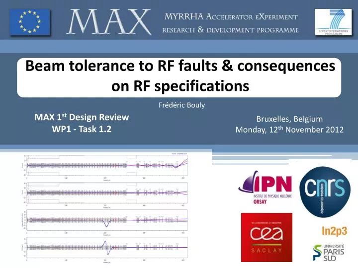
Beam tolerance to RF faults & consequences on RF specifications. Frédéric Bouly. MAX 1 st Design Review WP1 - Task 1.2. Bruxelles , Belgium Monday, 12 th November 2012. INTRODUCTION. Evaluate the minimum RF power required to enable fault-recovery procedures.

E N D
Beam tolerance to RF faults & consequences on RF specifications Frédéric Bouly MAX 1st Design Review WP1 - Task 1.2 Bruxelles, Belgium Monday, 12th November 2012
INTRODUCTION • Evaluate the minimum RF power required to enable fault-recovery procedures. • Take Margins as regard to control errors : cavity theoretical parameters (ex: (r/Q)), accuracy of control systems, measurement errors. • It depends on coupling (from the power couplers) - A choice has to be made for each section of the linac. • Re-tuning beam dynamic studies will give the new Vcavand ϕsfor each compensation cavity. • Carry out beam study based on the reference linac design to : • Give an exhaustive list of critical retuning cases • Evaluate the retuning feasibility • From these typical scenarios evaluate the power consumption of recovery cavities in every linac sections Starting point & Objectives MAX 4th General meeting, Frankfurt 12thNovember 2012 Bouly F.
Introduction • Beam tolerance to RF Faults • - Methodology • -Example : loss of a Spoke module • - Status on different critical cases • Couplings (Qi) choices • - PRF & Qi are directly linked • - Methodology • - Results & consequences • RF specifications • - Statistical study of errors • - RF power required for each section • Summary & Prospects MAX 4th General meeting, Frankfurt 12thNovember 2012 Bouly F.
Introduction • Beam tolerance to RF Faults • - Methodology • -Example : loss of a Spoke module • - Status on different critical cases • Couplings (Qi) choices • - PRF & Qi are directly linked • - Methodology • - Results & consequences • RF specifications • - Statistical study of errors • - RF power calculation for each section • Summary & Prospects MAX 4th General meeting, Frankfurt 12thNovember 2012 Bouly F.
Beam tolerance to RF Faults • Simulations are based on the linac reference design (“strong focusing”option 1) • (J-L. Biarrotte, “SC linac design & MEBT”) • I0 = 4 mA ; Beam input parameters from injection line • (C. ZHANG, “Injector layout & beam dynamics”) • Local compensation - Eacc nominal chosen to enable a ~30 % increase (based on the SNS): • 1 failed cavity (or 1 Cryomodule) is compensated by 2 cavities (or 2 Cryomodules) placed upstream & 2 cavities (or 2 Cryomodules) placed downstream. Method • Procedure developed during previous project : • PDS-XADS () : Procedure setup - Identification of the difficulty to apply local compensation below 15 MeV.(J-L. Biarrotte, D.Uriot ,M. Novati, P. Pierini , H Safa “Beam dynamics studies for the fault tolerance assessment of the PDS-XADS linac design” , EPAC 2004). • EUROTRANS : Transient effect study - Definition of dynamic retuning scenario (J-L. Biarrotte, D.Uriot,“Dynamic compensation of an rf cavity failure in a superconducting linac” , Phy. Review, May 1998). • The synchronous phases are kept in a range similar to nominal conditions (i.e. -40° ≲ϕs ≲ -15°), in order to try to keep the longitudinal acceptance of the linac. MAX 4th General meeting, Frankfurt 12thNovember 2012 Bouly F.
Beam tolerance to RF Faults 5-CELL ELLIPTICAL (β 0.47) SECTION TraceWin Calculations SPOKE SECTION Example : Failure of a spoke cryomodule (1/6) Failed module (2 cavities) Longitudinal size diagnostic 4 re-tuned modules (8 re-tuned cavities) Energy diagnostic Energy & Phase diagnostics MAX 4th General meeting, Frankfurt 12thNovember 2012 Bouly F.
Beam tolerance to RF Faults Cavities voltage Beam Energy Example : Failure of a spoke cryomodule (2/6) Synchronous phase Cavities RF power (Beam loading) MAX 4th General meeting, Frankfurt 12thNovember 2012 Bouly F.
Beam tolerance to RF Faults Nominal Tuning Fault-recovery Example : Failure of a spoke cryomodule (3/6) MAX 4th General meeting, Frankfurt 12thNovember 2012 Bouly F.
Beam tolerance to RF Faults Example : Failure of a spoke cryomodule (4/6) MAX 4th General meeting, Frankfurt 12thNovember 2012 Bouly F.
Beam tolerance to RF Faults Nominal Tuning Fault-recovery Example : Failure of a spoke cryomodule (5/6) Emittances (rms) Emittances (rms) Lattices phase advance Lattices phase advance MAX 4th General meeting, Frankfurt 12thNovember 2012 Bouly F.
Beam tolerance to RF Faults Longitudinal acceptance of the linac(SC linac + MEBT + HEBT) Example : Failure of a spoke cryomodule (6/6) Nominal Tuning Fault-recovery εacc/ εRMS ≈ 5.25/0.075 = 70 εacc/ εRMS ≈ 4.5/0.075 = 60 MAX 4th General meeting, Frankfurt 12thNovember 2012 Bouly F.
Beam tolerance to RF Faults Summary :studied scenarios - Failure of the last cavity - Failure of the last Cryomodule - Failure of 1 cavity - Failure of a Cryomodule - Failure of 1 cavity - Failure of a Cryomodule - Failure of 1 Cryomodule - Failure of 1cavity 11 identified scenarios - Failure of the 1st cavity - Failure of the 1st Cryomodule (in progress) - Failure of the last cavity Spoke β 0.35 5-cell β 0.47 5-cell β 0.65 MAX 4th General meeting, Frankfurt October 1st 2012 Bouly F.
Introduction • Beam tolerance to RF Faults • - Methodology • -Example : loss of a Spoke module • - Status on different critical cases • Couplings (Qi) choices • - PRF & Qi are directly linked • - Methodology • - Results & consequences • RF specifications • - Statistical study of errors • - RF power required for each section • Summary & Prospects MAX 4th General meeting, Frankfurt 12thNovember 2012 Bouly F.
Qi choice • Power delivered to the beam : Beam power & RF power amplifier • RF power required from the generator when cavities gets their optimal frequency tuning : with • Optimum for coupling : Ideally, each cavity would have its own power coupler with an optimised Qi(in function of its (r/Q), ϕs, Vcav & Ib0) • To calculate the RF power requirements, one has to first choose the coupling values for each of the 3 linac sections. • To find out the most adapted couplings : we look for the value of Qiwhich minimise Pg /Pb(i.e. which minimise the total RF power in nominal configuration) MAX 4th General meeting, Frankfurt 12thNovember 2012 Bouly F.
Qi choice Couplings choice & bandwidth 5-cell Spoke • Frequency bandwidth 5-cell • Spoke (β 0.35) : BW = 160.2 Hz • 5-cell (β 0.47) : BW = 86.05 Hz • 5-cell (β 0.65) : BW = 102.2 Hz MAX 4th General meeting, Frankfurt 12thNovember 2012 Bouly F.
Qi choice Impact on RF consumption Total RF power increase is negligible : 0.74% (from 2.335 MW to 2.352 MW) MAX 4th General meeting, Frankfurt 12thNovember 2012 Bouly F.
Qi choice • Once the Qi has been chosen it is therefore possible to calculate the RF power increase for the recoverycavitiesin the ideal case : the cavities frequency are perfectly tuned, errors & attenuations are not taken into account. Return on Spoke failure example MAX 4th General meeting, Frankfurt 12thNovember 2012 Bouly F.
Introduction • Beam tolerance to RF Faults • - Methodology • -Example : loss of a Spoke module • - Status on different critical cases • Couplings (Qi) choices • - PRF & Qi are directly linked • - Methodology • - Results & consequences • RF specifications • - Statistical study of errors • - RF power calculation for each section • Summary & Prospects MAX 4th General meeting, Frankfurt 12thNovember 2012 Bouly F.
RF specifications • RF generator power - general formula RF Power - Errors & Attenuations Example : Cavity n° 76 (β0.47) which is compensating a failure • Errors taken into account for statistical errors study 22.35 kW • Vcav : ± 2% • ϕs : ± 2° • Ib0 : ± 2% • Δf : ± 20 Hz • Qi : ± 2 mm (± 20%) • (r/Q) : ± 10 % • 2.106 draws • + 10 % marginsaddedfrom errors study to take into account attenuation and calibration errors. Maxi. 24.9 kW MAX 4th General meeting, Frankfurt 12thNovember 2012 Bouly F.
RF specifications Summary on RF needs MAX 4th General meeting, Frankfurt 12thNovember 2012 Bouly F.
Introduction • Beam tolerance to RF Faults • - Methodology • -Example : loss of a Spoke module • - Status on different critical cases • Couplings (Qi) choices • - PRF & Qi are directly linked • - Methodology • - Results & consequences • RF specifications • - Statistical study of errors • - RF power required for each section • Summary & Prospects MAX 4th General meeting, Frankfurt 12thNovember 2012 Bouly F.
Beam fault-tolerance to a module failure has been demonstrated in each section • Same simulation method applied in each scenario • A special tool should be developed to enable the calculation of the retuning set-points during the linac operation • One scenario to improve : failure of the 1st Spoke cryomodule - More tricky because bunchers before the failed module have to be retuned In progress • Carry out simulation with several fault-recoveries in the linac & include errors (misalignments ... ) Conclusions • The power coupler Qi requirements have been calculated : • Spoke section (β 0.35) : Qi = 2.2 106 BW = 160.2 Hz • Elliptical 5-cell (β 0.47) : Qi = 8.2 106 BW = 86.05 Hz • Elliptical 5-cell (β 0.65) : Qi = 6.9 106 BW = 102.2 Hz • Evaluation of the power requirements to anticipate on control errors + attenuations + fault-recovery scenarios : • Study with faults showed that a reasonable choice for the RF amplifier power would correspond to take a minimum margin of ~70 % (75% foreseen) compare to the nominal required Power (errors + attenuations + fault recovery). • Spoke section (β 0.35) : 15 kW • Elliptical 5-cell (β 0.47) : 30 kW • Elliptical 5-cell (β 0.65) : 55 kW • R&D activities for fault-recovery procedures study on a real scale experiment will be presented tomorrow. (R. PAPARELLA, “SC elliptical cavities design & associated R&D” - F. BOULY, I. MARTÍN, “Fault-recoveryprocedures & associated R&D”) MAX 4th General meeting, Frankfurt 12thNovember 2012 Bouly F.
THANK YOU ! MAX 3rd General meeting, Madrid 12thNovember 2012 Frédéric Bouly