Download
1 / 20
210 likes | 458 Vues
Partial Scan Design with Guaranteed Combinational ATPG. Vishwani D. Agrawal Agere Systems, Circuits and Systems Research Lab Murray Hill, NJ 07974, USA va@agere.com Yong C. Kim and Kewal K. Saluja University of Wisconsin, Dept. of ECE Madison, WI 53706, USA

E N D
Partial Scan Design with Guaranteed Combinational ATPG Vishwani D. Agrawal Agere Systems, Circuits and Systems Research Lab Murray Hill, NJ 07974, USA va@agere.com Yong C. Kim and Kewal K. Saluja University of Wisconsin, Dept. of ECE Madison, WI 53706, USA kimy@ece.wisc.edu and saluja@engr.wisc.edu
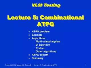
Overview 1. Problem statement 2. Background and previous work 3. Combinational ATPG for general acyclic circuits • Balanced model generation • Test generation – multiple-fault model • Results 4. Special classes of acyclic circuits • Internally balanced structure • Balanced structure • Strongly balanced structure • Results 5. Conclusion Partial scan with comb. ATPG
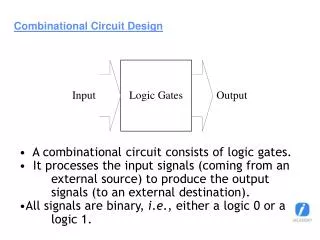
Problem Statement • Partial scan design has less DFT overhead, but is less desirable than full-scan because it requires sequential ATPG • Problem: To devise a combinational ATPG method for general acyclic circuits; cyclic structures can be made acyclic by partial scan FF1 FF2 FF2 A cyclic circuit Acyclic partial scan circuit Partial scan with comb. ATPG
Background and Previous Work Models for Acyclic Sequential Circuits • Iterative array model (Kunzmann and Wunderlich, JETTA, 1990): Logic duplicated as many times as sequential depth for combinational ATPG • Duplicated logic model (Miczo, 1986): Selective logic duplication still results in large combinational ATPG circuit • Pseudo-combinational model (Min and Rogers, JETTA, 1992): Shorting of flip-flops makes some faults combinationally untestable • Balanced structure (Gupta, et al., IEEETC, 1990): A sequential circuit structure with provable fault detection by combinational ATPG Partial scan with comb. ATPG
Relevant Results • Theorem (Bushnell and Agrawal, 2000): A test for a testable non-flip-flop fault in a cycle-free (acyclic) circuit can always be found with at most dseq+1 time-frames. • Balanced circuit (Gupta, et al., IEEETC, 1990): An acyclic circuit is called balanced if all paths between any pair of nodes have the same sequential depth. A test for any testable fault in a balanced circuit can be found by combinational ATPG. Partial scan with comb. ATPG
Present Contribution: Comb. ATPG for General (Unbalanced) Acyclic Circuits Generate a balanced model, map faults Generate a test vector for a target fault using combinational ATPG Obtain a test sequence from comb. vector Simulate circuit to drop detected faults Yes More faults to be detected? No Done Partial scan with comb. ATPG
An Example Unbalanced nodes a s-a-0 b FF dseq = 1 Combinational vector Balanced model 0 a0 s-a-0 0 1 X 1/0 b0 1 a-1 s-a-0 1/0 1/0 1 b-1 FF replaced by buffer Test sequence: 11, 0X Partial scan with comb. ATPG
s-a-1 Multiple stuck-at fault: lines a and b stuck-at 1 and line c stuck-at 0. An equivalentsingle stuck-at fault: output of AND gate stuck-at 1 s-a-1 s-a-1 s-a-0 a A A a B b B b c C C c A Single Fault Model for a Multiple Fault(New) Partial scan with comb. ATPG
Fault equivalence: Faulty output functions • Amf = 1 • Bmf = 1 • Cmf = 0 • Fault equivalence: Faulty output functions • Asf = a + 1 = 1 • Bsf = b + 1 = 1 • Csf = c · 0 = 0 s-a-1 s-a-1 s-a-1 s-a-1 • Circuit equivalence: Fault-free output functions • A = a + a ·b ·!c = a • B = b + a ·b ·!c = b • C = c ·!(a ·b ·!c) = c · (!a + !b + c) =c ·(!a + !b) + c = c s-a-0 a A A A a a B b B B b b c C C C c c Proof of Correctness for the New Model Partial scan with comb. ATPG
B A A A A TF=1 TF=0 TF=0 TF=1 TF=2 1 B B B C B 1 1 1 TF=1 TF=0 TF=2 TF=1 TF=0 FF2 FF2 1 1 FF2 1 Multiple fault mapping: A stuck-at fault of 1 is mapped onto a multiple fault 1 5 0 7 X 1 5 A 0 7 X 1 FF2 FF3 5 7 X 0 FF2 FF3 0 FF2 FF3 A 0 FF2 6 Y 1 B 1 6 Y 1 B 6 Y FF4 TF=2 FF4 3 4 3 C 4 FF4 B A 3 4 D Q D Q D Q D Q D Q D Q D Q D Q D Q D Q D Q D Q D Q D Q D Q D Q D Q D Q D Q FF2 FF3 1 C 5 A B 0 7 X 1 5 0 C 7 X 2 TF=1 2 FF2 FF3 FF1 2 FF1 FF1 FF4 6 Y B 6 Y 3 4 FF4 B C 3 4 C C FF1 2 2 FF1 Acyclic Circuit Combinational ATPG Example Partial scan with comb. ATPG
* Sun Ultra Sparc work station ISCAS ’89 Benchmark Circuit Result: S5378 • Circuit statistics • Number of gates: 2,781 • Number of FFs: 179 • Number of faults: 4,603 Partial scan with comb. ATPG
ISCAS’89 Circuits (Acyclic with Partial Scan)FC: cov. (%), FC: efficiency (%), VL: vec. Length, TGT: CPU s Sun Ultra Partial scan with comb. ATPG
ISCAS’89 Circuits (Acyclic with Partial Scan)Circuit statistics Partial scan with comb. ATPG
Subclasses of Acyclic Circuits • Balanced (B) circuit: A circuit in which all paths between any pair of nodes (PIs, POs, gates or FFs) have the same sequential depth (Gupta et al, IEEETC, 1990) • Acyclic circuit:A sequential circuit without feedback • Strongly balanced (SB) circuit: A balanced circuit which has same depth from any PIs to any reachable POs (Balakrishnan and Chakradhar, VLSI Design `96) • Internally balanced (IB) circuit: A circuit that becomes balanced by splitting of PI fanouts (Fujiwara et al., IEEETC, 2000) • Combinational circuit: A sequential circuit with full-scan Sequential Acyclic SB Combinational IB B Partial scan with comb. ATPG
Number of Scan FFs for Various Subclasses IB: Internally balanced (Fujiwara, IEEETC, 2000) B: Balanced (Gupta, et al., IEEETC, 1990) SB: Strongly balanced (Balakrishnan and Chakradhar, VLSI Design ’96) Partial scan with comb. ATPG
Fault Coverage for Acyclic Subclasses ATPG: Gentest (Cheng and Chakraborty, Computer, 1989) Partial scan with comb. ATPG
ATPG CPU Seconds for Acyclic Subclasses(Sun Ultra Workstation) ATPG: Gentest (Cheng and Chakraborty, Computer, 1989) Partial scan with comb. ATPG
Comb. And Sequential Vector Lengths Acyclic Balanced Internally bal. Strongly bal. Combinational VL: Number of combinational ATPG vectors CC: Sequential test clock cycles for scan sequences Partial scan with comb. ATPG
Conclusion • Using a balanced circuit model and combinational ATPG, we can generate tests for any acyclic sequential circuit with equal or higher fault coverage and efficiency than obtained by sequential ATPG. • For acyclic circuits, the new ATPG procedure provides comparable fault coverage and efficiency with significantly lower DFT ( partial-scan) overhead as compared to internally balanced, balanced, strongly balanced and combinational subclasses. Partial scan with comb. ATPG
Thank you Partial scan with comb. ATPG