Download
1 / 22
220 likes | 324 Vues
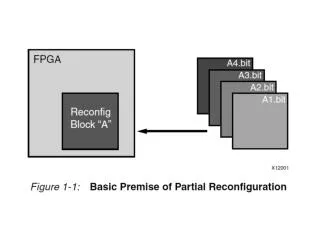
Partial Reconfiguration Not just a half baked job of reconfiguring. Rohit Kumar Research Student University of Florida. Dr. Ann Gordon-Ross Associate Professor of ECE University of Florida. Partial Reconfiguration is All Around Us. Changing situations….

E N D
Partial ReconfigurationNot just a half baked job of reconfiguring Rohit Kumar Research Student University of Florida Dr. Ann Gordon-Ross Associate Professor of ECE University of Florida
Partial Reconfiguration is All Around Us Changing situations… …require part of the system to reconfigure on the fly
Partial Reconfiguration is All Around Us • But, FPGA reconfigurationis disruptive • Resets the device • Lose all data • Causes downtime • Downtime is dangerous
Full Reconfiguration: This is your FPGA on PR This is your FPGA Static Task 1 Task 1 Task 2 Task 2
Why Partial Reconfiguration? • So what?? • I’ll just put both tasks on the same device! • Sure, why not? • But, devices have limited space! Not impressed Reason #1 Sharing many tasks on a single region saves area! FPGA Task 1 Task 2 Task 3 Task 4 Task 5 Task 6
Why Partial Reconfiguration? • I got it! I’ll just use PR on a tiny cheap FPGA and time-multiplex everything! • Okay, we’ll give you that one • But, it’s a trade off • The more parallelism, the better the performance • Plus, some tasks must be run in parallel Reason #2 Using less area on a smaller device is less costly!
Why Partial Reconfiguration? • So that’s it?? • I pay a bunch more just to use less area? • Well, you know you could save power? • Imagine you have two versions of a task • High-performance version • Low power version • When performance is critical • Load the high-performance version • When performance is less critical • Load the low-power one Man, what a buzz-kill Reason #3 Replace tasks with low-power versions when possible! FPGA
Why Partial Reconfiguration? • So what?? • I’ll just use clock gating (CG)and dynamic frequencyscaling (DFS), both of which are available for Xilinx FPGAs • Right… well… you see… actually…. Hmm… Shut up
Why Partial Reconfiguration? • Okay, but I’m not sold unless there are 4 reasons. • Did you know PR keeps your device safe in space? • In space, cosmic radiation corrupts SRAM! • These are called single event upsets (SEU)s • With PR, you can patch FPGA configuration memory • Without turning off the device • This is called “scrubbing” FPGA 10111011 FPGA 01101100 Reason #4 PR keeps circuits safe in harsh environments But FPGA configuration memory uses SRAM!
So you wanna make a PR design… • First, we make partitions • Partitions are like black boxes • They start out empty • Then we load modules • Modules run tasks • To change tasks • Load a new module • Old one is overwritten The FPGA(not to scale) Partition 2 f Partition 1 f a a b
So you wanna make a PR design… • Modules have to fit like puzzle pieces • Black boxes have a defined interface • All modules must fit that interface • Where the ports are matters as well • Ports must be in the same place for every module • “Partition pins” are port location definitions • They ensure connections are not broken during PR The FPGA(not to scale) Partition 2 f Partition 1 f a a b
So you wanna make a PR design… • Quit sugar-coating it, sirs, Iam not a child you know. • Oh, fine. This is what you’re going to learn today: • Logically partitioning your application into modules • Preparing your partitioned design in ISE • Floor-planning the layout of your device in PlanAhead • Implementing your design in PlanAhead • Finding your inner child through meditation (time permitting)
Step 1: Logical partitioning • Easy there buddy • Two components are mutually exclusive if • Only one is used at a time • One’s inputs don’t directly depend on the other’s outputs • Only mutually exclusive components share a partition • So, before you can make your design… • You must find as many of these as you can The first step to make a PR design is breaking the application into sets of mutually exclusive components
Step 1: Logical partitioning • Okay, lets do an example • This is an up/down counter • The add and the subtract • …are mutually exclusive • Only one is used • They do not depend on each other • The store and the add • …are not mutually exclusive • The store depends on the add’s output • The add and subtract can share a partition • The add forms one reconfigurable module • The subtract forms another reconfigurable module He’s still not reassured Direction = up Result = 0 Direction = up Result = 0 up down Direction? Result ++ PR! count Result ++ Result -- Result ++ Store Result Get Direction Store Result Get Direction
F4-13: Partially Reconfigurable System Development and Management Rohit Kumar Elizabeth Graham Aurelio Morales Shaon Yousuf Zack Smaridge Research Students University of Florida Dr. Ann Gordon-Ross Associate Professor of ECE University of Florida Number of supporting memberships: 1.5
F4-13: Goals, Motivations, and Challenges Increase reconfigurable computing (RC) system designer productivity Goal • Optimize area, power, and performance • Reduce design time effort Partial reconfiguration (PR) enables area and power savings Motivations • PR isolates reconfiguration to portions of FPGA • Enables resource time-sharing • Distributed computing provides increased system computation capability • Leverage network of PR-capable FPGAs • Leverage distributed resource management services • Early design space pruningreduces design time • Design automation enables rapid system implementation • Scripts and tools reduce manual design flow steps • Source code’s PR analysis aidsdesign parameter selection • PR requires application- and device-specific, low-level knowledge Challenges • Efficient design space exploration (DSE) for PR-centric system design • Identifying automatable design flow steps • Maintaining application data integrity across PR-centric distributed RC systems
F4-13: Approach Task A Task C Identifies resource- and performance-optimized PR architectures Enables distributed processing and management across VAPRES nodes One-clickPR Design SpaceExploration Node-Level DistributedResource Management • Adapt system-wide version of DDRM for server/client • Leverage dynamic hardware task management tools • Design and test DDRM application • Leverage PRML to generate PR applications from source code • Leverage high-level synthesistools to generate VHDL code • Leverage intermediate fabrics1and DAPR+2for fast DSE PR-centric RC System Development Automated Design Implementation Dynamic Hardware TaskManagement • Expand context save and restore (CSR) and hardware task relocation (HTR) features • Optimize CSR and HTR to maximize task throughput and resource utilization • Design automation tool suite (DAPR++) to aid PR system design • Generates distributed RC system for increased computational capacity Alleviates tool flow overhead and reduces implementation effort Enables load balancing across local and remote VAPRES nodes Task B 1 Developed by F2-10 2 Developed by F4-11 DSE – Design Space Exploration DAPR+ – Design Automation for PR FPGAs DDRM – Distributed Dynamic Resource Manger PRML – PR Modeling Language
Task A: PR Design Space Exploration Framework Streamlined framework for rapid application partitioning, PR design space exploration, and implementation Automatically generates PR application from non-PR high-level source code Explores PR design space to find area/power/ performance optimized PR application Alleviates complexities in PR design implementation via automated tool flows Automatically generates PR application from non-PR high-level source code Framework components Partitioning Automatic modeling and PR partitioning of application’s C source code via PRML1 Implementation Automation and integration of vendor’s and various third-party tools PR design space exploration Low-level automated floorplaning and partitioned application’s area/ power/performance evaluation 1 Published in FCCM’13
Task B: PR System Design Automation with DAPR++ Tool Suite • DAPR++ tool suite aids designing RC systems using automation Slave FPGA 1 Slave FPGA 2 Master FPGA • Creates master and slave FPGA component layout tree • Creates FPGA VHDL black boxes for all components PRRs PRRs GPP CAW13 Switch • Creates network protocols for master and slave FPGAs • Automatically generates target device resource mapping • Heuristically floorplans PRRs and partition pins CAW13 CMW12 • Creates PR task reconfiguration schedules to reduce reconfiguration time CAW13 • Modifies bitstreams and enables task context save (CS) and context restore (CR) • Records data packet transfer rates between master and slave FPGAs
Task C.1: Node-level DDRM • Node-level DDRM facilitates VAPRES network management • Automatically manages task relocation • Minimizes system delays caused by task relocation latency • Uses custom node communication procedures • Maintains global node execution status • Task relocation circumvents node-level restrictions • Individual nodes have limited resources and power • Network nodes to leverage shared resource pool • Example applications: sensor networks, target tracking • Node-level DDRM controls nodes’ task distribution • Node is a client for local tasks, server for remote tasks • Client determines new node and PRR for task execution • Algorithm developed in system-level test version of DDRM • Clients communicate with servers to locate new PRR and transfer PRM • Created automated communication functions to coordinate inter-node transfer of bitstreams, context, test results, and node status DDRM DDRM DDRM DDRM DDRM DDRM DDRM – Distributed Dynamic Resource Manager PRR – Partially Reconfigurable Region PRM – Partially Reconfigurable Module
Task C.2: Hardware Task Management Tools On-chip CSR On-chip HTR • Distributed processing and load balancing tools for networked VAPRES nodes • Portable across different FPGA architectures • On-chip context save and restore (CSR) and hardware task relocation (HTR) software • PRM execution state retained on PRM preemption • Enhances task switching in PR-capable FPGAs • Suitable for autonomous, multitasking PR systems VAPRES node M2 PRR1 PRR 1 • New CSR and HTR features • Supports DSPs/BRAMs/LUTRAMs and multiple PRR rows/columns • Reduced execution times VAPRES node merged M1 PRR2 • Experimental results on XUPV5 board • Linear growth rate in CSR execution times w.r.t. number of PRM flip-flops • HTR execution times • Linear growth rate for context save (CS) and context restore (CR) • Non-linear growth rate for task relocation (TR) • System designers can trade off PRR size/granularity and CSR/HTR execution times based on application requirements M1 PRR1 M2 PRR1 M1 PRR1 M1 PRR2 PRR 1 PRR 2 M3 PRR2 PRM – Partially Reconfigurable Module VAPRES – Virtual Architecture for Partially Reconfigurable Embedded Systems DSP – Digital Signal Processing BRAM – Random Access Memory Block PRR – Partially Reconfigurable Region