Download
1 / 38
380 likes | 389 Vues
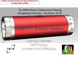
Project Co-financed by the Italian Ministry for Foreign Affairs (MAE). Short Status Report CGEM project. Collaboration Meeting (Beijing) June 4-7th, 2013. Outline CGEM simulation at BESIII Space available for CGEM installation CGEM prototype project Roadmap toward a CGEM-based IT

E N D
Project Co-financed by the Italian Ministry for Foreign Affairs (MAE) Short Status Report CGEM project Collaboration Meeting (Beijing) June 4-7th, 2013
Outline CGEM simulation at BESIII Space available for CGEM installation CGEM prototype project Roadmap toward a CGEM-based IT Collaboration activities from IHEP side (proposal) Next step for INFN – IHEP both sides (proposal)
中国科学院高能物理研究所 INSTITUTE OF HIGH ENERGY PHYSICS CGEM simulation at BESIII Dong Mingyi, Wang Liangliang, Xiu Qinglei
CGEM Geant4 Model Yellow: Honeycomb Support (Nomex) Blue: Cathode (Cu, Kapton) White: Work Gas of Gem (Ar:CO2=70:30) Green: Gem Foil (Cu, Kapton) Red: Readout Anode (Cu, Kapton, Al Shielding) Grey: Carbon Fiber Support
Detail Structure of CGEM Layer Single Mask Gem Foil, Single conical hole structure Hole diameter: 70-60 um The larger section of the holes facing the cathode. Hole Pitch: 140um
Preliminary reconstruction with CGEM inner detector Outer MDC hits CGEM fired strips CGEM true hits MDC tracking Cluster reconstruction smearing Track in outer MDC Kalman track fitter CGEM hits Kalman track with CGEM Quick test with different spatial resolutions
Expected spatial resolution sz srf From Italian group BESIII B-Field sz= 400 mm BESIII B-Field srf= 330 mm * Taken as expected spatial resolution
Momentum resolution type I and II refer to different layer configurations (cathode/anode reversed)
Conclusion CGEM inner detector (VS MDC inner detector) • Improves dz resolution significantly(by a factor of 2.6~6) • Comparable dr resolution (~5% poorer for low momentum tracks ) • Comparable momentum resolution (~5% better for high momentum tracks)
Space available for CGEM installation Mingyi Dong
Mechanical structure of inner MDC Inner drift chamber is fixed on the first step ring of MDC through two flanges
Space available for CGEM parts of the sense wires in this region are ineffective Parts of inner sense wires in z direction are out of the effective solid angle (cosθ= 0.93) Also available space when we consider CGEM installation
Suppose 3 layers CGEM • L1 length: 532mm , L2 length: 690mm • L3 length: 847mm
Space available in z direction 3 layers CGEM The gap is about 80mm~100mm between the end plate of MDC inner chamber and the mechanical support of beam pipe 105mm~235mm in z direction is available for thesupportstructure, readout electronics, cables of CGEM on each side
Summary • Space available for CGEM in r direction is about 63 (78?) mm ~183.5mm • If the length of CGEM matches the MDC effective solid angle (cosθ= 0.93), space available for CGEM in z direction is about 105mm~235mmon each side
MAE Funding (*) Italian Ministry for Foreign Affairs • June 2012: BESIII-Italy was invited by INFN management to apply for MAE(*) money in a program for Chinese-Italian scientific cooperation • BESIII-Italy prepared 2 projects: • BESIII-To: “mobility of researchers” (physics analysis) • BESIII-LNF: “great relevance” (construction of one layer of cylindrical GEMs with analogic readout) • Both projects have a BESIII-Chinese counterpart, submitted by BESIII-China to Chinese authorities • April 2013: projects approved by MAE for funding
The LNF project is for a total amount of 360 k€ divided over a period of 3 years. Every year MAE, INFN and IHEP contribute a budget of 40 k€ each MAE contribution for year “N” must be advanced by INFN in “N”, and refunded by MAE in “N+1” 2013: INFN will deliver in June the first 40 k€ of the 80 k€ expected (additional 40 k€ are expected later) These successes have motivated additional researchers from LNF and Torino and another INFN Institution, Ferrara, to apply for participation in BESIII. Good news!
New anode design KLOE2 IT – Readout Plane (no more available)
COMPASS-type solution: new readout electrodes 50 µm kapton Pitch X strips: 650 mm Width X strips: 350 mm Width V strips: 80 mm Kapton: 50 mm Cu: 5 mm • Due to diffusion the charge cloud collected on the readout board is bigger than the strip width (≈ 3.5 x pitch) and a weighting method is used for calculate the exact track position in two dimensions • Every single strip versus the other readout coordinate acts as a plate capacitor. With the permittivity ε=3.9 of Kapton and an area of 2.27⋅10-1cm2, this capacitance is 15.7 pF
Prototype roadmap to 2015 • 2013 • Cosmic ray setup: construction • Clean room preparation • Cylindrical prototype: design and tool construction • 2014 • Cosmic ray setup: run and analysis • Cylindrical prototype: construction and assembly • 2015 • Cylindrical prototype: test (cosmic rays and beam)
Prototype roadmap: Activities 2013-2014 A cosmic test setup (LNF-FE) The COMPASS-type readout layer is substantially different from the KLOE2 one It must be tested, before employ in a full-scale cylindrical prototype KLOE2 can give us a cosmic-ray telescope (3 complete and working planar GEM chambers of KLOE2 type) To these we will add a small (10x10 cm2) planar chamber with GEMs, and a COMPASS-type readout layer
Buy planar GEM chamber kit from CERN Prepare support for readout layer Design and order COMPASS-type small readout layer Procure GASTONE, TOFPET analogic chips, etc. Buy boards for DAQ (ADCs or digitizers) Start taking cosmic data, beam if possible Small rate if few channels: will take time
CGEM Prototype • Start simulations with Garfield and Maxwell (LNF-FE) • Test COMPASS-type readout plane with GASTONE analog chips (LNF-FE) and TOFPET using an amplifier • GASTONE analog chips can’t be used in BESIII • Start preliminary operations for construction of cylindrical prototype (LNF-FE) • Develop DAQ for small test chamber (FE) • Develop offline for small test chamber (LNF-FE) • Test rohacell-based technique for cathode construction for the innermost layer and start a mockup CGEM (FE)
Mechanics (FE-LNF-IHEP) Refurbish clean room, repair toolings etc Evaluate KLOE2 machine for inserting cylindrical layers (BESIII layers may be longer) Examine possibility to use KLOE2 molds for BESIII middle layer. Modify or rebuild if necessary! IHEP experienced manpower is strongly needed Start drawings for COMPASS-type readout layer
Electronics, DAQ, Offline, HV, gas system Start ASIC development for BESIII (TO-LNF) Design off-detector electronics (LNF) Start studying impact on BESIII DAQ and L1 trigger (IHEP) Monte Carlo and Offline Reconstruction (IHEP, LNF, FE, TO) Plan additions to HV, Gas systems, Slow Controls (IHEP)
IT FrontEnd electronics Plan (TO) • Readout ASIC for CGEM: • Modify/adapt the existing TOFPET ASIC (Rolo, Rivetti et al http://iopscience.iop.org/1748-0221/8/02/C02050) in IBM 130nm for PET applications • Re-design a new analogue FE (suited for CGEM signals) • Use of the same BackEnd of TOFPET • Migration to a newer and cheaper technology: IBM 130nm UMC 110 nm should be exportable in China (implemented in Italy) • Integration and Development of such a Custom ASIC for CGEM
Man Power is a critical Issue: • VLSI Lab at INFN-TO, led by A. Rivetti, has expertise on HEP applications • Required Man Power to work at VLSI Lab in Torino: - 3y*1FTE (PhD with electronics background) for testing/test bed AND - 2y*1FTE (experienced engineer in electronics) for chip development
ASIC Basic features: • UMC 110 nm technology (limited power consumption, to be tested for radiation tolerance) • Time and Charge measurements by independent TDCs • TDC 50ps time binning • Double threshold discrimination • Time over Threshold (ToT) to measure the charge • Power consumption~ 7 mW p/channel
FE and Off-Detector Electronics roadmap • 2013 • Planar GEM telescope instrumentation (signal & HV) • Readout electrodes simulation (parasitic minimization study) • TofPet asic (IT readout candidate) validation • 2014 • IT prototype anode readout plane design (early 2014) • IT HV distribution and signal pick-up engineering (front-end integration) • Design of a new version of TofPet asic (different input stage to increase signal sensitivity and SNR) – 2 foundry submission foreseen • Off Detector Electronic design (end 2014) • Readout boards and Concentrators • HV distribution boards (minimize the number of HV primary channels) • IT prototype (sectors) instrumentation by means of existing asics developed for analog readout (APV25 ?) • 2015 • New version of TofPet asic validation on CGEM IT prototype • Off Detector Electronics e HV design • IT front-end (TofPet) integration • 2016 • On Detector (asic & boards) and Off Detector electronics production/test • 2017 • IT instrumentation and validation 32
Roadmap toward a CGEM-based IT • 2013 • start R&D program (cosmic setup, simulations) • write a Letter of Intent • 2014 • build prototype with IT middle layer layout • 2015 • Prototype test and validation • TDR • IT design and material procurement • 2016 • start IT construction • 2017 • complete IT, test and validation
Cooperation activities from IHEP side (proposal) • verification of Manpower for: • building prototype • designing FE electronics • implementing simulation and offline • making DAQ and Slow Controls • built up HV • preparing Gas System • installing CGEM
Next step (proposal) • Preparation of a Letter of Intent for INFN-IHEP cooperation on CGEM • Establishing a INFN-IHEPCGEM Steering Committee
Letter of Intent (I) • The present BESIII Drift Chamber • Description • Status of Inner Chamber • Present and future (high-Lum) problems for data taking • Estimation of backgrounds • Present backgrounds: measurements • Future backgrounds: simulations • The Cylindrical GEM technique: advantages and drawbacks • The KLOE2 Inner Tracker • Material budget • Analog vs. digital, expectations and measurements • Projects: geometry and layout • Simulation of Cylindrical GEM Tracker • Parametric simulations • Single particle simulations • Problematic channels simulations
Letter of Intent (II) • Frontend electronics • The KLOE2 electronics • Requirements for BESIII • Impact on DAQ • Dead time • Disk space • Requirements on trigger • Intermediate level trigger • Offline reconstruction • Money, manpower, times, tasks subdivision.....