Download
1 / 11
110 likes | 230 Vues
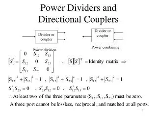
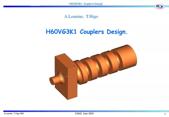
A.Lounine, T.Higo. H60VG3K1 Couplers Design. MDK-2001. CERN Switzerland. Input Coupler. r = 0.5. Output Coupler. 10.12. 10.35. r = 0.5. Matching Cell. T 0m = 5 2A 0m = 15.52. 2B 1m = 24.2. T53 m = 4.8 2A53 m = 13.82. T 1 = 4.53732 2A 1 = 10.7947. 2B 53m = 23.2. Matching Cell.

E N D
A.Lounine, T.Higo H60VG3K1 Couplers Design. MDK-2001 CERN Switzerland
Input Coupler r = 0.5 Output Coupler 10.12 10.35 r = 0.5 Matching Cell T0m= 5 2A0m= 15.52 2B1m= 24.2 T53m= 4.8 2A53m= 13.82 T1= 4.53732 2A1= 10.7947 2B53m= 23.2 Matching Cell • All dimensions are at 20C • Calculation frequency is 11.429 GHz
Equidistant Manual Mesh Generation Tetrahedras ~ 300.000 Azimuth rotation step = 2 degree ! Automatic ANSOFT mesh generator produces too much nonuniform mesh; ! As a result – poor convergency, poor field’s output
Tipical HFSS simulation for output coupler * E[V/m] is normalized for 1 Wt input power (a quarter geometry!)
Output CouplerSurface Fields ~3.5% iris field enhancement Surface path * E[V/m] is normalized for 1 Wt input power (a quarter geometry!)
N.Kroll Method of Reflection and Phase Advance Simulation Results Input Coupler Output Coupler
RF Load Experemental Setup S11, S21 HP 8510C Network Analizer Matching cell Reflection = S11 + S12 S22, S12
Input Coupler. HFSS&Experemental Results* * Experimental results are shifted to the calculation conditions (20C, vacuum)
Output Coupler. HFSS&Experemental Results* * Experimental results are shifted to calculation conditions (20C, vacuum) ** Due to technical mistake the measurement was done with wrong RF-load diameter
Output Coupler. Base Parameters Tolerances, HFSS Simulations
Final Remarks. • H60VG3 is low group velocity structure , therefore couplers bandwidth is very narrow. • The mesh parameters are very critical to final results. • The 3D Mesh parameters were obtained from 2D analog. • The phase advance was strictly cheked at each calculation step (<0.5 degree). • Hook-Jeevs method + frequency sweep were used for couplers optimization. • The measurement results are in good agreement with the calculated ones. • The most sensitive dimension is B (outer radius). The accuracy of Bn dimensions • should be better then 2 μm.