Download
1 / 27
270 likes | 436 Vues
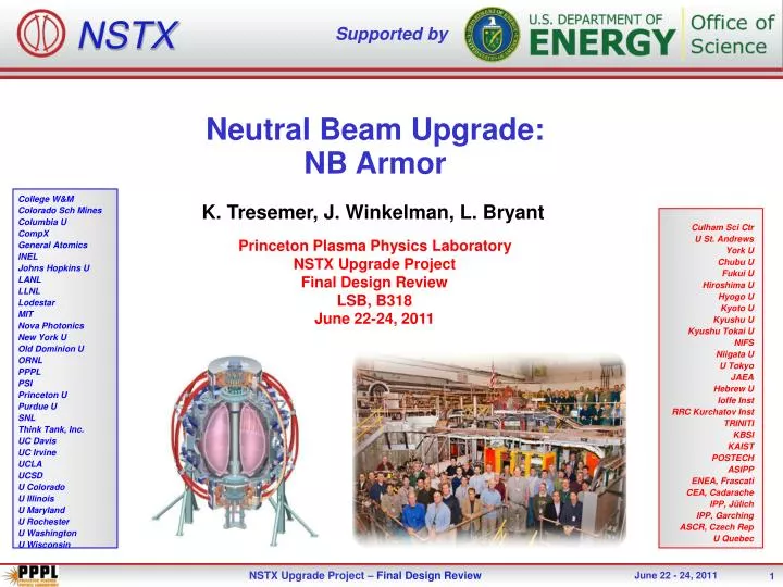
NSTX. Supported by. Neutral Beam Upgrade: NB Armor. College W&M Colorado Sch Mines Columbia U CompX General Atomics INEL Johns Hopkins U LANL LLNL Lodestar MIT Nova Photonics New York U Old Dominion U ORNL PPPL PSI Princeton U Purdue U SNL Think Tank, Inc. UC Davis

E N D
NSTX Supported by Neutral Beam Upgrade: NB Armor College W&M Colorado Sch Mines Columbia U CompX General Atomics INEL Johns Hopkins U LANL LLNL Lodestar MIT Nova Photonics New York U Old Dominion U ORNL PPPL PSI Princeton U Purdue U SNL Think Tank, Inc. UC Davis UC Irvine UCLA UCSD U Colorado U Illinois U Maryland U Rochester U Washington U Wisconsin K. Tresemer, J. Winkelman, L. Bryant Culham Sci Ctr U St. Andrews York U Chubu U Fukui U Hiroshima U Hyogo U Kyoto U Kyushu U Kyushu Tokai U NIFS Niigata U U Tokyo JAEA Hebrew U Ioffe Inst RRC Kurchatov Inst TRINITI KBSI KAIST POSTECH ASIPP ENEA, Frascati CEA, Cadarache IPP, Jülich IPP, Garching ASCR, Czech Rep U Quebec Princeton Plasma Physics Laboratory NSTX Upgrade Project Final Design Review LSB, B318 June 22-24, 2011 1
Outline • Design Specs • Design Overview • Summary • Analysis Summary & Results • Overview • Thermal: • Beamline footprint projection • Armor Faults for 1 and 2 beamlines • Cooling analysis for normal operations • Mechanical: • Disruption analysis • Thermal growth of backing plates • Project Summary
Design Specifications • This job covers the removal, upgrade, and re-installation of the NSTX-U NB Armor to serve as a calibrative surface and as protective armor for the Vacuum Vessel. • Armor has been designed in accordance with the NSTX-U General Requirements Document (GRD) and been analyzed for upgrade thermal and electromechanical loads. • GRD calls for the evaluation and any necessary modification of the NB Armor to make it suitable for operation with a second Neutral Beamline. • Armor was evaluated and re-designed to NSTX-U NBI power loads, as specified per the GRD.
NB Armor Design Overview • Armor Relocation: • Shifting armor counterclockwise • To fit both beamlines on surface • Using ATJ graphite in non-crucial areas of armor. • Carbon Fiber Composite (CFC) in areas of intense beam overlap • Upgrading mounting hardware to maximize port functionality and installation/removal • Look at disruption forces and resulting stresses on armor mounts • Project Tree: 145 drawings • 75 part drawings, all complete • 57 Assembly drawings, all complete • 13 Hardware drawings, all complete
Armor Move • Current Alignment • Proposed Alignment • BL 1 • BL 2 • BL 1 • Bay I • Bay I • Bay H • Bay H • Bay G
Armor Mounting System • Front • Welded studded pads (4 places) • MSE LIF Port • Bay I Mount • Bay G Mount
Armor Mounting System • Back • Bay I support • Bay G support • Bay H supports
Armor Analysis Overview • Daily Operations: • Armor will see negligible heat flux from plasma • Same as First Wall: 0.06 MW/m2 • MSE calibrations will not change from present • 90 kV shot, for 400 ms, single source • Very low thermal loading • Shinethrough? • Not an issue, a small fraction of a single source • Fault Condition: • A “runaway” beam shot, for the duration of that shot • HIGHLY unlikely event • Can only occur when plasma is not present in vacuum vessel • Would occur only if plasma interlocks fail • Both single and double NB faults analyzed WRT the NB armor
Analysis: Thermal • Thermal • Beamline source fit on armor • Ensuring that all 6 sources fit appropriately on armor face • Locate any areas of overlap (and high heat flux) • Fault condition evaluation of the Armor tiles • 1 and 2 beamlines • Evaluations of between-shot cooling during normal operations • Confirm that residual heat is removed during a 1200 sec rep rate.
Thermal Analysis: Beamline Source Fit • Beamline Sources simulated to test fit on NB Armor and to estimate source heat flux at armor face. • Used combination of empirical data and analysis to create beam “footprints” • Beam photo shows rough ellipse shape from conditioning shots • Assumed beam dispersion of .5 deg horizontal, 1.5 deg vertical from last scraping surface. • Used calculated “Smear” areas for beam profiles (incident angle effects) • Taking these areas, built ellipses and applied them to a simple armor shape, showing beam layout and overlaps • C • B • A
Thermal Analysis: Beamline Source Fit • Resulting Source Profiles on Armor Face Confirms Fit! • Outer ring: • 20% total source power • Inner “hotspot”: • 80% total source power • Beam overlaps create areas of intense flux • Area of thermal investigation and probable material upgrade to 3D CFC
Thermal Analysis: Fault Condition Evaluation • Model accuracy check • Data from MSE shots • ATJ tiles • 90 kv, 19 MW/m2 source heat flux, 400 ms • 50 – 80 C bulk temp change • Confirmed that ALGOR model behaved similarly • 1 NB “fault” testing • Temperature and Stress under full power, full length of shot • 80 kV, 7.7 MW/m2, 5 sec • 90 kV, 9.2 MW/m2, 3 sec • 110 kV, 13.9 MW/m2, 1 sec • Baseline Material properties of ATJ Graphite • Max Tensile Strength: 26 MPa • Max Compressive Strength: 66 MPa • Max Temp : 2600 °C* *This is the temperature at which the sublimation rate rapidly accelerates. Sublimation does begin at lower temperatures in vacuum, but the effect is less. Attempting to capture an acceptable maximum temperature.
Thermal Analysis: Fault Condition Evaluation • 2 NB “fault” testing • Temperature and Stress under full power of two beams • Looking at an overlap tile that sees greatest flux • Finding time limit to max temp and max stress • 80, 90, 110 kV
Thermal Analysis: Fault Condition Evaluation • Results • Single NBL “fault” is acceptable • Temperatures and stresses within capabilities of ATJ graphite • Possible surface cracks, ablation • If occurs, should attempt to visually inspect surface for damage • Double NBL “fault” is not acceptable with only ATJ • Stresses on surface and in T-slot exceed material limit • Risk critically cracking tile. Need to prevent this. • Use available CFC in needed zones. Tensile strength 3x that of ATJ. • Temperatures will surpass 2600 ºC and carbon will rapidly sublimate. • Material mass will be sufficient to protect for length of “fault”. Stainless backing plates added protection. • Armor will be damaged, need visual inspection, but will perform duty as a sacrificial protective surface. • Increased safety: • Additional plasma interlock • Increasing SS backing plate coverage • Increased administrative caution while using both NBLs
Thermal Analysis: Between-Shot Cooling • Used a “worst case” heat load on tile and backing plate • 1000°C bulk temp. Extremely conservative. • Ran test sample in ALGOR, simple shape • “Back of the envelope” Analysis • 3”x1” slice of armor (tile and backing plate), 3/8” cooling tube, 20 minutes between shots • Determined time constant for cooling: ~70 seconds • Results show cooling system adequate for in-between shot cooling
Thermal Analysis: Between-Shot Cooling • Graphite (ATJ) • Stainless Steel
Analysis: Mechanical • Mechanical • Disruption analysis of the armor array • Conservative model • Analysis of thermal expansion of backing plates and possible resultant interferences • Highest plate temp occurs during 150 ºC bakeout
Neutral Beam Armor Solid Model • The Solid Model is Symmetric about 2 planes • Only ¼ of Armor model will be included in the FE analysis
Transient Dynamic Von Mises Stress (Outboard Displacement Disruption) • Plate Support • Vessel Interface • Weld Interface • Vessel Edge 1 • Bolt Stress • Flange 1 • Vessel Edge 2 • Max Stress = 1.6e7 Pa = 2,320 psi • Flange 2 • The Transient Equivalent Stress at Max Current is less than 10 Ksi • and well within the material strength capacity (Based on Merged Solids)
Thermal Growth • Addressed potential thermal growth issues with the new armor constraints • Used bake-out temps as an example • Shows that SS plates grow “up and out” • Do not cause tile interference
Thermal Growth • Addressed potential thermal growth issues with the new armor constraints • Used bake-out temps as an example • Shows that SS plates grow “up and out” • Do not cause tile interference • Direction of Thermal Growth
Conclusions • Thermal • 6 sources fit adequately upon armor face • In areas of high heat flux (source overlaps), tile material will be replaced with 4D CFC • CFC has multi-plane high k, thermal shock resistance, good mechanical properties • Armor will sufficiently protect the VV from NB exposure, even with increased heat flux from source overlap • Cooling lines will be adequate for heat removal between shots
Conclusions • Mechanical • New mounting scheme improvement to accessibility • Employing bay H and G as access points • Disruption analyses show that forces in the mounts are low, material and fasteners are adequate for loading • Consider final analysis with updated load scenarios and non-merged model • Thermal growth in plates will not cause issues with tiles • Other • Installation and Assembly procedures are being created • Armor drawings are complete. • NBI Armor design is finalized, analysis is complete, ready to move to procurement.
The End • Questions?
Supplemental Slides • NBI Power to Plasma/Beamline
Shinethrough • Most likely Source for shinethrough: BL2 A • BL2 A runs along the edge of some plasmas • In a “skinny” plasma, shinethough might occur. • Not a problem! • BL2 A hits CFC and thermal issues are nominal. • BL 2 • BL 1 • A • B • A • C • B • C