Download
1 / 30
300 likes | 437 Vues
NSTX. Supported by. Multipoint Thomson Scattering (MPTS). George Labik M. Denault, H. Feder , M. Smith. College W&M Colorado Sch Mines Columbia U CompX General Atomics INEL Johns Hopkins U LANL LLNL Lodestar MIT Nova Photonics New York U Old Dominion U ORNL PPPL PSI

E N D
NSTX Supported by Multipoint Thomson Scattering (MPTS) George Labik M. Denault, H. Feder , M. Smith College W&M Colorado Sch Mines Columbia U CompX General Atomics INEL Johns Hopkins U LANL LLNL Lodestar MIT Nova Photonics New York U Old Dominion U ORNL PPPL PSI Princeton U Purdue U SNL Think Tank, Inc. UC Davis UC Irvine UCLA UCSD U Colorado U Illinois U Maryland U Rochester U Washington U Wisconsin Culham Sci Ctr U St. Andrews York U Chubu U Fukui U Hiroshima U Hyogo U Kyoto U Kyushu U Kyushu Tokai U NIFS Niigata U U Tokyo JAEA Hebrew U Ioffe Inst RRC Kurchatov Inst TRINITI KBSI KAIST POSTECH ASIPP ENEA, Frascati CEA, Cadarache IPP, Jülich IPP, Garching ASCR, Czech Rep U Quebec Princeton Plasma Physics Laboratory NSTX Upgrade Project Final Design Review LSB, B318 June 22-24, 2011 1
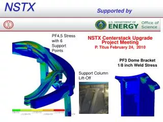
MPTS CSU • The MPTS is a multi-time, multi-spatial point Thomson Scattering diagnostic for measuring the electron temperature and density profiles on the National Spherical Torus Experiment (NSTX) ST research facility. In 2009 the US Department of Energy approved the initiation of a project to upgrade the NSTX for approved performance. As a result, a new larger Center stack (CS) is being designed to provide enhanced operating capabilities. It is necessary to upgrade the MPTS to accommodate the new CS and provide MPTS coverage of NSTX Upgrade plasma operation. The vacuum boundaries closest to the vacuum vessel (VV) define the extent of this design review . Vacuum boundaries include torus interface valves, vacuum windows and blank covers. The Bay L port includes a number of diagnostics vacuum interfaces besides MPTS since they impact the port design but are not themselves part of this review. The VV interfaces cost is estimated at $967 K .The installation is to be completed in mid 2013. The cost and schedule details are covered in the project summary elsewhere. A successful PDR was conducted on 9 May 2011. The MPTS VV FDR is planned for late August 2011. 2
The ex vessel components which define the remainder of MPTS is a separate job. The work approval form has been submitted for management review and approval. The MPTS vacuum vessel modification at Bay L resulted in a design incorporating reinforcement of the VV at Bay JKLA, the MPTS FDR will include the optimization of the Bay L vacuum vessel reinforcement required to mitigate stresses from the upgrade enhanced operation. The optimization is proceeding in response to a chit from the PDR concerning the effect of the reinforcement on the Resistive Wall Mode (RWM) coils performance. MPTS CSU 3
Background CHERS • Field of View • TIV • Bellows • Bay L • FIReTIP • Ceramic • Break • Laser MPTS – Isometric View- Vessel Section 5 • Laser input • Vacuum interface • Bay F • Collection Optics • Box
NSTX Test Cell 6 • Bay F • Laser Optics Box • Laser Dump • Bay L • N
Existing Lasers Path MPTS – X Section 1 of VV – Overlay New and Existing Laser Centerlines 7 • New Lasers Path
MPTS-X Sect 2 VV – Overlay New and Existing Laser Centerlines 8
MPTS-X Sect 3 VV-Overlay of New and Existing Laser Centerlines 9
Laser Optics Box MPTS _ Test Cell and Vacuum Vessel 10 • Laser flight tube • Bay L TIV and Structural Support
MPTS-Test Cell looking South West_ Laser Dump 11 • Vacuum window • MPTS – View Looking South _ Bay L and Laser External Dump • Machine vacuum • Remote ly Operable • Laser Mirrors • Laser dump • Bay L
Bay F • Calibration probe • VV Interface MPTS – Laser input _ VV Interface 1 12 • Vacuum Window • And Aperture • Fiber Bundles • Fiber Array • Lasers VV Interface • Collection Optics Box
Elliptical Plug • 1.5 Inch Thk. MPTS – Laser VV Interface 2 13 • Fiber Array • Adjustment and Support
Upgrade Center Stack MPTS _ Laser and Background CHERS 16 • Bay L • VV Interface • Background CHERS • Field of view
MPTS – Laser Spacing 17 • RWM Coils • Vertical Members • 1.5 inches additional toroidal space provided
MPTS • High K • scattering MPTS – Bay L 19 • 12 inch OD • Tube • El Break • Back • CHERS • Bellows • TIV • SPRED • XEUS • FIReTIP
Laser dump tube MPTS – Bay L 20 • Steering • Mirror
Existing • FIDA Diagnostic • Typical cutout for PF coils • J • L • A • K 22 • Typical i/2 inch thick plate • On vessel shell • Bridging Bar • 3 x 4 inches • Reinforcement components
K • A • J • L 23 • Typical ½ thick plate • On vessel shell • Reinforcement components
MPTS-Bellows 28