Download
1 / 1
10 likes | 143 Vues
Surface Orientation of Chiral Liquid Crystals. 7.6µm Mylar Spacer. Top Surface. CC/CM Mixture. ZLI-4330. Field of view of microscope at 5x optical zoom. Liquid Crystal. Results. Bottom Surface. UV Epoxy Divider. 7.6µm Mylar Spacer.

E N D
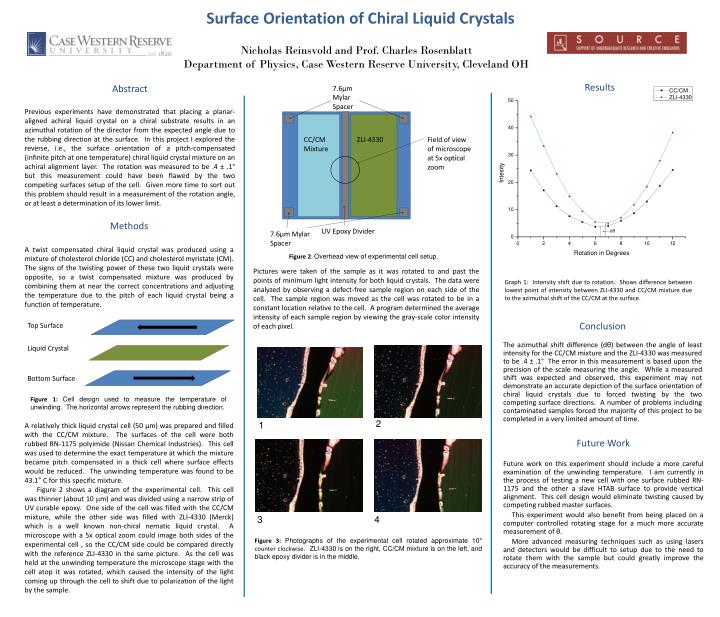
Surface Orientation of Chiral Liquid Crystals 7.6µm Mylar Spacer Top Surface CC/CM Mixture ZLI-4330 Field of view of microscope at 5x optical zoom Liquid Crystal Results Bottom Surface UV Epoxy Divider 7.6µm Mylar Spacer Nicholas Reinsvold and Prof. Charles RosenblattDepartment of Physics, Case Western Reserve University, Cleveland OH Methods A twist compensated chiral liquid crystal was produced using a mixture of cholesterol chloride (CC) and cholesterol myristate (CM). The signs of the twisting power of these two liquid crystals were opposite, so a twist compensated mixture was produced by combining them at near the correct concentrations and adjusting the temperature due to the pitch of each liquid crystal being a function of temperature. dθ Figure 2: Overhead view of experimental cell setup. Pictures were taken of the sample as it was rotated to and past the points of minimum light intensity for both liquid crystals. The data were analyzed by observing a defect-free sample region on each side of the cell. The sample region was moved as the cell was rotated to be in a constant location relative to the cell. A program determined the average intensity of each sample region by viewing the gray-scale color intensity of each pixel. Graph 1: Intensity shift due to rotation. Shows difference between lowest point of intensity between ZLI-4330 and CC/CM mixture due to the azimuthal shift of the CC/CM at the surface. Conclusion The azimuthal shift difference (dθ) between the angle of least intensity for the CC/CM mixture and the ZLI-4330 was measured to be .4 ± .1° The error in this measurement is based upon the precision of the scale measuring the angle. While a measured shift was expected and observed, this experiment may not demonstrate an accurate depiction of the surface orientation of chiral liquid crystals due to forced twisting by the two competing surface directions. A number of problems including contaminated samples forced the majority of this project to be completed in a very limited amount of time. Abstract Previous experiments have demonstrated that placing a planar-aligned achiral liquid crystal on a chiral substrate results in an azimuthal rotation of the director from the expected angle due to the rubbing direction at the surface. In this project I explored the reverse, i.e., the surface orientation of a pitch-compensated (infinite pitch at one temperature) chiral liquid crystal mixture on an achiral alignment layer. The rotation was measured to be .4 ± .1° but this measurement could have been flawed by the two competing surfaces setup of the cell. Given more time to sort out this problem should result in a measurement of the rotation angle, or at least a determination of its lower limit. Figure 1: Cell design used to measure the temperature of unwinding. The horizontal arrows represent the rubbing direction. A relatively thick liquid crystal cell (50 µm) was prepared and filled with the CC/CM mixture. The surfaces of the cell were both rubbed RN-1175 polyimide (Nissan Chemical Industries). This cell was used to determine the exact temperature at which the mixture became pitch compensated in a thick cell where surface effects would be reduced. The unwinding temperature was found to be 43.1° C for this specific mixture. Figure 2 shows a diagram of the experimental cell. This cell was thinner (about 10 mm) and was divided using a narrow strip of UV curable epoxy. One side of the cell was filled with the CC/CM mixture, while the other side was filled with ZLI-4330 (Merck) which is a well known non-chiral nematic liquid crystal. A microscope with a 5x optical zoom could image both sides of the experimental cell , so the CC/CM side could be compared directly with the reference ZLI-4330 in the same picture. As the cell was held at the unwinding temperature the microscope stage with the cell atop it was rotated, which caused the intensity of the light coming up through the cell to shift due to polarization of the light by the sample. 2 1 Future Work Future work on this experiment should include a more careful examination of the unwinding temperature. I am currently in the process of testing a new cell with one surface rubbed RN-1175 and the other a slave HTAB surface to provide vertical alignment. This cell design would eliminate twisting caused by competing rubbed master surfaces. This experiment would also benefit from being placed on a computer controlled rotating stage for a much more accurate measurement of θ. More advanced measuring techniques such as using lasers and detectors would be difficult to setup due to the need to rotate them with the sample but could greatly improve the accuracy of the measurements. 3 4 Figure 3: Photographs of the experimental cell rotated approximate 10° counter clockwise. ZLI-4330 is on the right, CC/CM mixture is on the left, and black epoxy divider is in the middle.


