Download
1 / 21
230 likes | 382 Vues
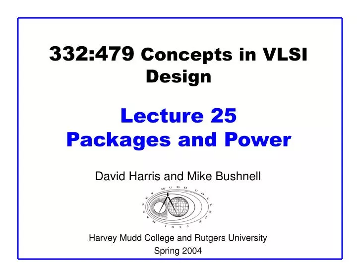
332:479 Concepts in VLSI Design Lecture 25 Packages and Power. David Harris and Mike Bushnell Harvey Mudd College and Rutgers University Spring 2004. Outline. Packaging Power Distribution Summary. Material from: CMOS VLSI Design , by Weste and Harris, Addison-Wesley, 2005. Packages.

E N D
332:479 Concepts in VLSIDesignLecture 25Packages and Power David Harris and Mike Bushnell Harvey Mudd College and Rutgers University Spring 2004
Outline • Packaging • Power Distribution • Summary Material from: CMOS VLSI Design, by Weste and Harris, Addison-Wesley, 2005 Concepts in VLSI Des. Lec. 25
Packages • Package functions • Electrical connection of signals and power from chip to board • Little delay or distortion • Mechanical connection of chip to board • Removes heat produced on chip • Protects chip from mechanical damage • Compatible with thermal expansion • Inexpensive to manufacture and test Concepts in VLSI Des. Lec. 25
Packaging • Main issues: • Cost • Thermal Impedance – how effectively package removes heat from the die • Lead Inductance • Ceramic pin grid array package – lowest • Cheap epoxy plastic – highest Concepts in VLSI Des. Lec. 25
Package Types • Through-hole vs. surface mount Concepts in VLSI Des. Lec. 25
Multi-Chip Modules • Pentium Pro MCM • Fast connection of CPU to cache • Expensive, requires known good dice Concepts in VLSI Des. Lec. 25
Chip-to-Package Bonding • Traditionally, chip is surrounded by pad frame • Metal pads on 100 – 200 mm pitch • Gold bond wires attach pads to package • Lead frame distributes signals in package • Metal heat spreader helps with cooling Concepts in VLSI Des. Lec. 25
Advanced Packages • Bond wires contribute parasitic inductance • Fancy packages have many signal, power layers • Like tiny printed circuit boards • Flip-chip places connections across surface of die rather than around periphery • Top level metal pads covered with solder balls • Chip flips upside down • Carefully aligned to package (done blind!) • Heated to melt balls • Also called C4(Controlled Collapse Chip Connection) Concepts in VLSI Des. Lec. 25
Package Parasitics • Use many VDD, GND in parallel • Inductance, IDD Concepts in VLSI Des. Lec. 25
Heat Dissipation • 60 W light bulb has surface area of 120 cm2 • Itanium 2 die dissipates 130 W over 4 cm2 • Chips have enormous power densities • Cooling is a serious challenge • Package spreads heat to larger surface area • Heat sinks may increase surface area further • Fans increase airflow rate over surface area • Liquid cooling used in extreme cases ($$$) Concepts in VLSI Des. Lec. 25
Thermal Resistance • DT = qjaP • DT: temperature rise on chip • qja: thermal resistance of chip junction to ambient • P: power dissipation on chip • Thermal resistances combine like resistors • Series and parallel • qja =qjp +qpa • Series combination Concepts in VLSI Des. Lec. 25
Thermal Impedance • Ceramic pin-grid arrays – 15 to 30 oC/Watt • Plastic Quad Flat Packs – 40 to 50 oC/Watt • Heat dissipation: • Finned heat sinks • Embedded metal slugs • High-cost packages: • Forced air or liquid cooling through package ducts • Example: IBM Thermal Conduction Module Concepts in VLSI Des. Lec. 25
Example • Your chip has a heat sink with a thermal resistance to the package of 4.0° C/W. • The resistance from chip to package is 1° C/W. • The system box ambient temperature may reach 55° C. • The chip temperature must not exceed 100° C. • What is the maximum chip power dissipation? Concepts in VLSI Des. Lec. 25
Example • Your chip has a heat sink with a thermal resistance to the package of 4.0° C/W. • The resistance from chip to package is 1° C/W. • The system box ambient temperature may reach 55° C. • The chip temperature must not exceed 100° C. • What is the maximum chip power dissipation? • (100-55 C) / (4 + 1 C/W) = 9 W Concepts in VLSI Des. Lec. 25
Power Distribution • Power Distribution Network functions • Carry current from pads to transistors on chip • Maintain stable voltage with low noise • Provide average and peak power demands • Provide current return paths for signals • Avoid electromigration & self-heating wearout • Consume little chip area and wire • Easy to lay out Concepts in VLSI Des. Lec. 25
Power Requirements • VDD = VDDnominal – Vdroop • Want Vdroop < +/- 10% of VDD • Sources of Vdroop • IR drops • L di/dt noise • IDD changes on many time scales Concepts in VLSI Des. Lec. 25
Power System Model • Power comes from regulator on system board • Board and package add parasitic R and L • Bypass capacitors help stabilize supply voltage • But capacitors also have parasitic R and L • Simulate system for time and frequency responses Concepts in VLSI Des. Lec. 25
Bypass Capacitors • Need low supply impedance at all frequencies • Ideal capacitors have impedance decreasing with w • Real capacitors have parasitic R and L • Leads to resonant frequency of capacitor Concepts in VLSI Des. Lec. 25
Frequency Response • Use multiple capacitors in parallel • Large capacitor near regulator has low impedance at low frequencies • But also has a low self-resonant frequency • Small capacitors near chip and on chip have low impedance at high frequencies • Choose caps to get low impedance at all frequencies Concepts in VLSI Des. Lec. 25
Power & Clock Conductor Sizing • Check for metal migration at worst power corner • Do the following checks: Concepts in VLSI Des. Lec. 25
Summary • Packaging • Power Distribution Concepts in VLSI Des. Lec. 25