Download
1 / 35
360 likes | 1.13k Vues
Portable Heart Rate Monitor & Arrhythmia Detector. Enyinnaya Egejuru December 3, 2008 Senior Design Project. Instructor: Prof. Swenson. TA: Bob Schoonover. Section 1. Introduction . Objective.

E N D
Portable Heart Rate Monitor & Arrhythmia Detector EnyinnayaEgejuru December 3, 2008 Senior Design Project Instructor: Prof. Swenson TA: Bob Schoonover
Section 1 Introduction
Objective Design a portable monitoring system able to acquire a biological signal (ECG) and detect abnormality from the regular sinus rhythm • Provide Immediate notification of abnormalities • Low cost and low power • Accessibility • User friendliness
Project Significance/Market This portable system will be useful whenever there is need for a low cost and low power monitoring system. Possible markets: • Third world countries • Poor Medical Infrastructure, facilities and equipment • Unreliable power supply • Quick, portable monitoring • Warfront
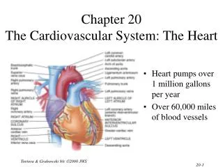
The Natural Pacemaker • The Sino-Atrial node (SA node) is a group of cells positioned on the wall of the right atrium • Cells in the SA node depolarize simultaneously resulting in contraction • Atrial contraction leads to the P-wave and the ventricular contraction leads to the QRS complex
Section 2 System design (FRONT END)
Block Diagram MSP430FG4618 AD622 LM358 ALARM
Electrodes (Signal Acquisition) • Interface between body and measuring/monitoring device. • Serve as transducer to change ionic current in body to electrical current • Electrolyte gel (AgCl) used to maintain good contact to skin • Pair used to measure potential difference between 2 parts of the body
ECG Signal Amplifier AD622 Instrumentation amplifier chosen for initial signal amplification. Heart beat signal ranges from 1mV – 4mV, need amplification to about 1V
ECG Signal Amplifier Cont’d • Gain of 10 from signal source, RG should be 5.62KΩ:
Biosignal from electrodes Signal from Instrumentation Amplifier
Analog Filters Filters are used to attenuate certain frequencies • 0.05Hz High Pass Filter: Filters voltage drift to reduce baseline wander and amplifier saturation • 130Hz Low Pass Filter: Remove high frequency noise and muscle artifact Cutoff Frequency determined by:
Analog Filters Cont’d • For High Pass: RC ≈ 3. Hence, Rhp = 100KΩ, Chp = 30µF • For Low Pass: RC ≈ .001. Hence, Rlp = 10KΩ Clp = 100pF • Further amplification (factor of 100) is done using a LM358 OP AMP
ECG Signal After Amplification This signal shows a real BioSignal coming from a test subject
MSP430FG4618 • Low supply-voltage range, 1.8V-3.6V • Ultralow power consumption • Five power saving modes • Wake up from standby mode in less than 6µs • 16 bit RISC architecture • 12 Bit A/D and 12 Bit D/A converters • 16 bit Timer_A • 116KB+256B Flash or ROM memory, 8KB RAM
Section 3 System design (core/software)
MSP430FG4618 MCU Software The figure above is a block diagram showing the function of the MCU
Digital Filter Design The MCU uses a high pass and a low pass filter • Fastest Deflection is the QRS complex. It lasts for about 20ms and has a frequency of 6Hz-30Hz • FIR filters were used because they are more stable • 17 tap FIR filter was implemented. Although higher taps would be better, we are working with limited resources • Filter design done using Matlab
Digital Low Pass Filter This filter was built using the filterbuilder functionality of Matlab. Coefficients are determined and convolution is performed
Digital High Pass Filter This filter was built using the filterbuilder functionality of Matlab. Coefficients are determined and convolution is performed
Heart Rate Calculation • Sample rate of 512 Hz. Allowing up to 10 samples or QRS complex. • Tracking of timescale using a variable (pulseperiod) • Output of QRS discriminator compared against threshold • Due to real-time need, pulseperiod is accumulated over 3 beats Heartrate per minute = 1/[pulseperiod/(3 x 512 x 60)] = 92160/pulseperiod
Section 4 System design (backend)
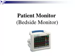
NOTIFICATION The Winbond® ISD17120 ChipCorder® is a highquality, fully integrated, single-chip multimessage voice record and playback device Ideally suited to a variety of electronic systems • 120sec messages at 8Khz sampling frequency • PWM class D speaker driver • LED blinking notification during playback • Multiple message addressing • Playback enabled by signal from MCU • Great sound quality during voice playback using 54c6
Section 5 TESTING and simulation
ECG Simulation • Was able to get ECG simulated WAV files • Testing of circuit for tachycardia and bradycardia could be easier as database has records of such arrhythmias • WAV files are transferred to circuit via a modified speaker phone. The right and left ear pieces correspond to the right arm and left arm
LCD Heart Rate Display • New feature added to design • LCD displays a readable heartrate to user. This helped me in testing and figuring out what was going on in the MCU
Other Testing • Oscilloscope reading at each amplification stage • Setting test levels for tachycardia and bradycardia to check response of notification pin • Using an LED to tell when heartbeat has gone above or below normal • Artifact from movement and electrodes
Section 6 Successes, challenges, and recommendations
Successes • Adequately acquire Biosignal • Adequately amplify Biosignal • Proper ADC conversion • Semi Functional Heart Rate counter • Proper notification functionality • Adding new feature (LCD for rate display) • Using Low Power components for battery operation • Used a new device in ECE445 (MSP430) and also performed core functionality in MCU • Low power. System powered with a 3V battery (2x1.5)
Challenges • Sophisticated QRS/Thresholding algorithm with the amount of resources we have in a microcontroller • Poor Skin/Electrode interface • Artifact • Amplifier issues • Offset voltages • Open Lead wires • Electric field interference
Recommendations • Digital 60Hz Notch Filter to reduce power line noise • A more sophisticated algorithm for QRS detection and heart rate calculation exists, but requires more resources (which will affect battery life) and is challenging to implement in a microcontroller
Thanks to… • Dr. Gary Swenson Instructor • Bob Schoonover TA • Kenneth Gentry ECE415 Instructor • ECE Parts Shop personnel • ECE Stores personnel • Spencer Brady ECE420 TA • My Fellow ECE445-its