Download
1 / 30
300 likes | 623 Vues
An Effective Hardware Architecture for Bump Mapping Using Angular Operation. Seung-Gi Lee † , Woo-Chan Park, Won-Jong Lee, Tack-Don Han, and Sung-Bong Yang Media System Lab. (National Research Lab.) Dept. of Computer Science Yonsei University. Contents. Introduction

E N D
An Effective Hardware Architecture for Bump Mapping Using Angular Operation Seung-Gi Lee†, Woo-Chan Park, Won-Jong Lee, Tack-Don Han, and Sung-Bong Yang Media System Lab. (National Research Lab.) Dept. of Computer Science Yonsei University
Contents • Introduction • Background and related work • Bump mapping algorithm • Vector rotation • Illumination calculation • Hardware architecture • Experimental results • Conclusions
Contents • Introduction • Background and related work • Bump mapping algorithm • Vector rotation • Illumination calculation • Hardware architecture • Experimental results • Conclusions
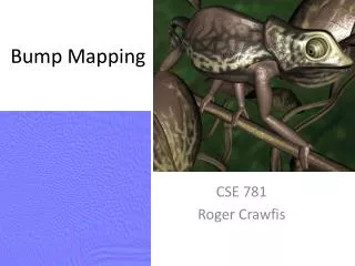
Background: bump mapping • Represent the bumpy parts of the object surface in detail using geometry mapping without complex modeling • Three steps • Fetch the height values from a 2D bump map • Perturb the normal vector N • Calculate the illumination with three vectors, the perturbed vector N’, the light vector L, and the halfway vector H • A large amount of per pixel computations is required.
Background: reference space • The normal vector perturbation can be preprocessed by defining the surface-independent space (reference space). [Peercy et al., Ernst et al.] • Instead, transformations from the object space into the reference space should be provided for each pixel (or for each small polygon). • Definition of a 33 matrix & a 33 matrix multiplication • The normalization of the vectors for the illumination calculation is also required.
Background: polar coordinates • Representation of a vector P • P = (P, P) • P is an angle between the x-axis and a vector Q • P is an angle between P and the z-axis • An effective approach from the viewpoint of hardware requirements [Kim et al., Ikedo et al., Kugler] • Only two angles • No normalization of vectors • However, the matrix multiplication for the transformation or a large map for the normal vector perturbation are still required.
Previous work related with PCS • Support bump, reflection, refraction, and texture mapping in a single LSI chip [Ikedo et al.] • Classical straightforward method require a large amount of logic for matrix operations • May produce the incorrect reflection angle to calculate the intensity of specular light • IMEM: integrate the arithmetic units and the reference tables into one dedicated memory chip [Kugler] • Support the simple normal vector perturbation method • Reduce the amount of computations by using the pre-computed LUTs and maps • However, a map of large size over 3 Mbytes is required
Previous work related with PCS • Hardware architecture supporting the bump-mapped illumination by using the Phong illumination hardware [Kim et al.] • Give a small reduction to the hardware requirements for the illumination calculation
Overview of this paper • We propose a new transformation method and present its hardware architecture. • Direct transformation of the vectors into the reference space • No hardware for matrix transformation, but only a few hardware logics for the vector rotations • Also, we present an effective illumination calculation hardware. • Use of “the law of cosine”
Contents • Introduction • Background and related work • Bump mapping algorithm • Vector rotation • Illumination calculation • Hardware architecture • Experimental results • Conclusions
Processing flow • Vector rotation stage • 3D object space 3D reference space • Use of the angular operation • Use of the projection onto the plane and the proportion onto the sphere • Bump vector fetch stage • The perturbed normal vectors are fetched from the bump vector map. • Illumination calculation stage • The inner products are computed. • The illumination is calculated by referring to the diffuse and specular tables.
Vector rotation The first rotation: -jN around the z-axis The second rotation: -N around the y-axis • The polar coordinates of the normal vector N are used as the rotation angles. • A corresponds to a light vector L and a halfway vector H. • The first rotation makes it possible to rotate accurately around the y-axis. • As a result, A in the object space is transformed into Aref in the reference space.
Geometric information • Geometric information required to find the polar coordinate (jA’, A’) of the transformed vector A’ • The calculation of x
Calculation of jA’ • The projection of A’ onto the xy-plane is required to find an angle jA’
Geometric relationship for A’ • We assume two arbitrary vectors that begin with the origin and end with points at which the plane in parallel with the xz-plane intersects the circles, Cm and . • The geometric relationship of the vectors on a sphere • When these vectors move on Cm and Cmyz under the above assumption, the ratio of the angular variation to the variation range of each vector for Cm is equal to that of .
Calculation of prop • can be calculated by using an angle of . • The projection of Amn and its related components onto the yz-plane • The y coordinate of a point at which the extension line of intersects a unit circle C0 in the yz-plane is y0/rm.
Calculation of A’ • Geometric information required to find the polar coordinate (jA’, A’) of the transformed vector A’ • X, Y, Z • The law of cosine
Illumination calculation • Phong illumination model • In order to calculate the inner products of the vectors, the vectors should be transformed into the vectors in the Cartesian coordinates. • The inner products of the transformed vectors are calculated as follows.
Illumination calculation • The number of multiplications 6 2 • The number of cosines 10 6 • However, applying the law of cosine to these equations makes it possible to reduce the amount of computations for the inner products.
Contents • Introduction • Background and related work • Bump mapping algorithm • Vector rotation • Illumination calculation • Hardware architecture • Experimental results • Conclusions
Proposed bump mapping hardware • The illumination calculation unit consists of two parts that calculate the intensities of the diffuse and the specular light. • The intensities of lights are obtained from the light tables referred to by the values of the inner products. • This unit can be implemented with 6 cosine tables, 1 diffuse table, 1 specular table, 2 multipliers, and 13 adders. The calculation of the inner products • Light table method • The table entries are indexed by scalar values. • The size of the table is 2816 ~21016 bits.
Vector rotation unit , where • This unit can be implemented with 6 tables, 3 multipliers, and 8 adders. • For arbitrary values of yk’s, θprop’s are precomputed by the following equation. • θprop’s are fetched from Tprop with the indices of yk’s.
Contents • Introduction • Background and related work • Bump mapping algorithm • Vector rotation • Illumination calculation • Hardware architecture • Experimental results • Conclusions
Experimental results • We modified Mesa 3.0 to implement the conventional method and the proposed method. • To differentiate the image qualities, we have performed texture- and bump-mapping using various objects with various maps. • In case of wooden wall, there is little difference in the quality between these two images, to the extent of not being differentiated by the naked eyes. Wooden wall : mapping onto a plane The conventional method The proposed method Brick wall : mapping onto a cube Map of the world : mapping onto a sphere
Experimental results • There is also little difference in the image quality as in the case of the previous simulation. Wooden wall : mapping onto a plane The conventional method The proposed method Brick wall : mapping onto a cube Map of the world : mapping onto a sphere
Experimental results • The images don’t look vivid because these mapping methods wear the maps converted from 512256 resolution into 512512 resolution on the surface of the object. • However, we can hardly differentiate the image quality between these two images. Wooden wall : mapping onto a plane The conventional method The proposed method Brick wall : mapping onto a cube Map of the world : mapping onto a sphere
Contents • Introduction • Background and related work • Bump mapping algorithm • Vector rotation • Illumination calculation • Hardware architecture • Experimental results • Conclusions
Conclusions • Bump mapping method with the effective vector rotation and illumination calculation algorithm. • Reduce a large amount of computations and hardwares • Generate nearly the same quality of images as the conventional method
Thank you!!! • We appreciate NRL project supported from the Ministry of Science & Technology of Korea. • NRL Project homepage • http://msl.yonsei.ac.kr/3d/ • E-mail address • sklee@kurene.yonsei.ac.kr