Download
1 / 24
240 likes | 353 Vues
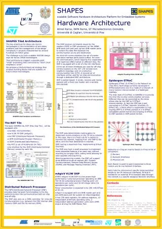
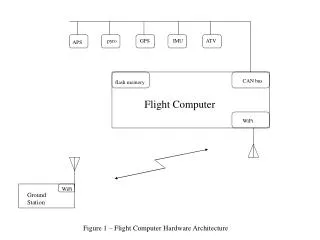
DDAQ Hardware Architecture. Jean-Sebastien Graulich, Geneva. General Architecture Tracker Baseline TOF Baseline & Options EmCal Baseline & Options Trigger Baseline Summary. DAQ Architecture. Trigger. distribution. Tracker. EmCal. TOF. VME Crates. Trigger + Ckovs. Optical link.

E N D
DDAQ Hardware Architecture Jean-Sebastien Graulich, Geneva • General Architecture • Tracker Baseline • TOF Baseline & Options • EmCal Baseline & Options • Trigger Baseline • Summary Jean-Sébastien Graulich
DAQ Architecture Trigger distribution Tracker EmCal TOF VME Crates Trigger + Ckovs Optical link Linux PCs Ethernet GigaBit Switch Remote Storage Online Online Storage Event Builder Monitoring Run Control Jean-Sébastien Graulich
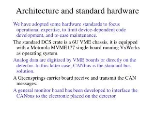
Hardware Consequences • PCs are sitting in the MICE LCR • -> VME crates are also sitting in the MICE LCR Cable transmission of • Analog Signal or • Digital Signal Jean-Sébastien Graulich
MICE layout Drawing by Tony Jones
Tracker • Sensors: VLPC • Front End Electronics (without AFE-t): • Analog to Digital: AFE II boards sitting on the cryo-cooler • Digital Data Buffer: VLSB (512 ch/module, 4 modules/cryo-cooler) • Number of Channels • 2 x 4096 ADC Jean-Sébastien Graulich
Tracker Connection Scheme (half a tracker) Fibers from VLPCs 4 VLSB Boards in VME Crate 27+x m (Tracker 1) or 12+x m (Tracker 2) Digital Signal 4 AFE Boards 1 Cryo-Cooler MIL1553 MICE HALL MICE LCR • Question: Where is the AVNET card located ? Jean-Sébastien Graulich
TOF Baseline • Sensors: TOF0: Hamamatsu R4998 TOF1 and TOF2: R4998 or R7761 (depending on Magnetic field shielding) R4998 Jean-Sébastien Graulich
TOF Baseline • Front End Electronics: • Constant Fraction Discriminator CAEN V812 (16 ch, ECL output) • TDC CAEN V1290 (32 ch, ECL or LVDS Input) • Number of Channels • 112 TDC (48 + 32 + 32) • No ADC in the Baseline Jean-Sébastien Graulich
TOF Baseline • TOF Connection Scheme (1 Station) HV Power Supply 1.5 TDC in VME SHV Cable BNC Cable (RG213) TriggerLogic 48 PMTs 3 CFD in VME Crate MICE HALL MICE LCR 30+x m (TOF 0) or27+x m (TOF 1) or 12+x m (TOF 2) • Question: Is CFD going to be precise enough ? • See other options Jean-Sébastien Graulich
TOF Options • Timing is affected by the signal amplitude • 2 Usual Solutions: • Use Constant Fraction Discriminator (CFD) • Measure amplitude and correct Time Walk Time Walk Correction Thresh. Time over threshold Example from Harp Jean-Sébastien Graulich
TOF Options Option 1. Constant Fraction Discriminator (CFD) The time walk is corrected automatically in the discriminator Threshold value depends on the amplitude • Advantage: Easy Cabling and No ADC • Drawback • No information at all on the charge (Energy Deposit) • Cost: TDC + ~ 125 EUR/ch (CFD) BNC Cable CFD TDC PMT Trigger Logic Jean-Sébastien Graulich
DISCRI TDC BNC Cable Splitter PMT Trigger Logic Cable Delay QDC Gate Signal TOF Options Option 2. Measure the Charge with a QDC • Advantage: More Precise andGood Charge Measurement • Drawback • General MICE ADC problem (No suitable QDC exists yet!) • Requires Splitters • More cabling • Cost: TDC + ~ 125 EUR/ch (DISC) ~ 200 EUR/ch (QDC) ~ Delay Cables (~20 m/ch)(Assuming free splitters) Jean-Sébastien Graulich
TOF Options Option 3. Measure the Charge with any available Solution • Same Advantages and Drawbacks as 2. • Cost: TDC + ~ 125 EUR/ch (DISC) ~ ??? EUR/ch (ADC) ~ Delay Cables (~20 m/ch)(Assuming free splitters) Jean-Sébastien Graulich
TOF Options Option 4. Measure the Charge with Time Over Threshold Principle • Advantage: Easy Cabling andCharge Measurement (not linear though)Good Precision for Time Walk Correction • NINO = ASIC developed by CERN/MIC for Alice TOFDiscriminator with ToT “proportional” to the Charge (at low amplitude) Proven technique, providing 50 ps resolution (IEE TNS Vol 51-5 (2004) 1974-1978)Very Cheap: 2 EUR/ch • Drawback • Requires Board development ! • Cost: TDC + Discri. board production (~50 EUR/ch) TDC PMT NINO Rising edge + Trailing edge Time Measurement Trigger Logic Width ~Charge Jean-Sébastien Graulich
EmCal Baseline • Sensors: Hamamatsu R1355 (100 in hand, Ludovico is trying to find the other 140…) Modified for differential output (100 Ohms) Jean-Sébastien Graulich
EmCAl Baseline • Front End Electronics: • Splitters • Discriminators • TDC: CAEN V1190 (128 ch, ECL or LVDS input) • ADC: No Baseline defined yet • Number of Channels • 240 ADC • 120 TDC in the Baseline Time information is useful for • Hit Position information in the direction // to the slab • Suppression of muon decay background (the muons are stopped in the EmCal and ready to decay when the next muon arrives, disturbing PID) -> My personal feeling: TDC needed for all the channels Jean-Sébastien Graulich
EmCal Baseline • EmCal Connection Scheme (Half EmCal) Charge measurement HV Power Supply SHV Cable Delay Twisted Pair Cable Transformer 120 PMTs Splitter MICE HALL MICE LCR 12+x m 4 Discriin VME 1 TDC in VME Jean-Sébastien Graulich
EmCal Options • Transformer • Needed to adapt the differential output of the PMt (twisted pair, 100 Ohm) to the Coaxial (Lemo, 50 Ohm) of the Splitter. • Splitter • It is possible to reuse active splitters developed in Sofia for HARP. 200 channels available • If we have enough charge, the transformer can also be made as a passive splitter with 1 differential input and two coaxial ouputs. Jean-Sébastien Graulich
EmCal Charge Measurement Options Option 1. Conventional gated QDC • Advantages • Familiar, proven design • Standard VME board, well documented • Support from the company (CAEN), the equipment have a long live after MICE • Drawbacks • The module does NOT exist yet, prototype could be delivered at the end of the year • Cost • Transformers + Discriminators (125 EUR/Ch) + TDC ( 60 EUR/ch) + QDC (200 EUR/ch) + Delay Cables Jean-Sébastien Graulich
EmCal Charge Measurement Options Option 2. QIE (TeV IPM) • Advantages • Probably no need for delay cable • The transformer can probably be included in the front end board (if we re-layout the board…) • Could be used for TOF (or CKOV) charge measurement • Drawbacks • Development Risk • Not VME readout, makes the DAQ more tricky. Probably OK but who knows… • Cost • + QIE FEB (??? EUR/ch) + PC BC (??? EUR/ch) + Discriminators (125 EUR/Ch) + TDC ( 60 EUR/ch) Jean-Sébastien Graulich
EmCal Charge Measurement Options Option 3. 200 MHz Flash ADCs • Advantages • No Splitter, no delay, no discri, no TDC ! • Cabling very easy • Equipment has a long after MICE life • Drawbacks • Transformer -> Shaper • Time resolution ? • Cost • Flash ADC (450 EUR/ch) + Shaper ( ??? EUR/ch) + VME Crate (6 kEUR) Shaper Vthr tthr >30 ns rise time 2 ns rise time If we can fit the rising edge, time resolution can be much higher than the 5 ns of the sampling rate. Jean-Sébastien Graulich
Readout Trigger Baseline • 6 Event Types: • Normal Event (RF ON or RF OFF) • Start of Spill • make sure the DAQ is ready for Normal Event • End of Spill • should Contain the relevant MCM data • Empty Event (Pedestals) • Pulser Events • Cosmic/Source Events • 1 trigger receiver input per Event Type • 1 trigger receiver output per Event Type (busy) + 1 common • Trigger receiver is a simple VME IO Register (4 kEUR/Unit) Jean-Sébastien Graulich
Particle Trigger Baseline • 3 Particle Trigger conditions for Normal Events • Beam: Burst x TOF0 • Timing given by TOF0 • Upstream: Beam x TOF1 • Timing given by TOF1 • Traversing: Upstream x TOF2 • Timing given by Upstream TOFn is defined by a twofold coincidence of the OR of the 12 (8) slabs of a single layer • Should be possible to add Traversing Muon, using EmCal information • If it’s really only these 4 conditions, there is no need for PLU. One simple I/O register is enough • Option: CMAC PLU (available in Geneva). Requires CAMAC-VME or CMAC PCi Interface • For Empty and Pulser Events, the particle trigger is generated by the DAQ system • For Cosmic Events, the particle trigger is set up locally by the subsystem who wants it Jean-Sébastien Graulich
Summary • Tracker Baseline has to be updated for AFEt • TOF Baseline is well defined and several options will be tested • EmCal Baseline is not clear (Charge measurement) • Trigger Baseline is well defined, no problem expected there Jean-Sébastien Graulich