Download
1 / 26
260 likes | 476 Vues
Digital Cochlea Model Implementation Using Xilinx XC3S500E Spartan-3E FPGA. Isabel Gambin, Ivan Grech, Owen Casha, Edward Gatt and Joseph Micallef Department of Microelectronics and Nanoelectronics University of Malta. Overview. Biological Cochlea Cochlear Model Digital Filter Design

E N D
Digital Cochlea Model Implementation Using Xilinx XC3S500E Spartan-3E FPGA Isabel Gambin, Ivan Grech, Owen Casha, Edward Gatt and Joseph Micallef Department of Microelectronics and Nanoelectronics University of Malta
Overview • Biological Cochlea • Cochlear Model • Digital Filter • Design • Design Verification • Implementation • Block Diagram • Multiplier Module • Adder Module • Results • Filter Chain • Design • Implementation • Block Diagram • Results • FPGA Usage • ADC Interface • Conclusion
Biological Cochlea • Basilar membrane – performs filtering action on incoming sound waves due to its varying parameters. Comparable to a spectrum analyser. • Inner hair cells – the mechanical neural transducers of the human auditory system. • Outer hair cells – provide positive feedback into the membrane to amplify otherwise inaudible sounds. Comparable to an AGC system. A cross-sectional view of the Cochlea [1]. An approximate frequency map of the basilar membrane in kHz [1].
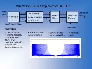
Cochlear Model • Basilar membrane modelled by a cascade of scaled filter stages. • The filter stages are tuned at frequencies following an exponential distribution. • The model covers the human auditory range from 20 Hz to 20 kHz. • Inner hair cells’ functionality is mimicked by taps set at regular intervals along the chain. • Outer hair cells are typically modelled by a controllable Q- factor in the filter’s transfer function.
Digital Filter: Design Digital Architecture of an IIR second-order filter module [2]. • 2nd order IIR low-pass filter • Transfer function in analogue domain: • Bilinear transform applied to map from s-plane to z-plane: • Frequency warping is taken into account using: • Comparable to the normalised generic transfer function: • For implementation purposes the difference equation is utilised:
Digital Filter: Design Verification • MatworksMatlab is utilised to perform verification on two levels: • that the bilinear transform is applied correctly • that the filter displays the required characteristics
Digital Filter: Implementation • Implements the filters’ difference equation using multiplier and adder sub-modules. • Six sets of internal registers for storing past input and output values due to time multiplexing scheme. • Filter index identifies the filter stages in the chain. • Hence, it is used for proper loading of coefficients and to access the right set of registers.
DFX Representation Used • Uses a single bit exponent to choose between two fixed point representations, lower Num 0 range and a higher Num 1 range • DFX representation implemented is 19_16_8 (n_p0_p1) • n - word length • p0/p1 - positions of the radix from the LSB for the lower and higher range respectively.
Multiplier module (1) • Computes product terms in filters’ difference equation • Based on dedicated 18-bit input multiplier blocks available on the FPGA • Coefficient input is in fixed point (FX) representation 18_16 (m_pm) • Sample input and output are in dual-fixed point (DFX) representation 19_16_8 (n_p0_p1) • The Range Detector Equation was adapted throughout to test the range:
Multiplier module (2) • Algorithm focuses on two main cases: • Case1: DFX input has E = 0 • Case2: DFX input has E = 1
Multiplier Module: Results • Using Xilinx ISim simulator, VHDL testbenches where implemented to verify the operation of the Multiplier Module for different exponent combinations. • Two such cases are:
Adder module (1) • Performs addition of product terms. • All inputs and output are in dual-fixed point (DFX) representation 19_16_8 (n_p0_p1) • Particular attention is paid to inputs with different exponents so as to scale them accordingly before performing addition.
Adder module (2) • Algorithm focuses on two main cases: • Case1: All inputs have same exponent • Case2: Inputs have different exponents
Adder Module: Results • Using Xilinx ISim simulator, VHDL testbenches are implemented to verify the operation of the Adder Module for different exponent combinations. • One such case is:
Digital Filter: Results (1) • Tests to verify correct functionality of filter module when all the registers in a particular set are in use. • Tests t0 confirm correct switching between sets of registers to retrieve the past input and output values according to filter stage index. • Input signals, output signals and contents of sub-modules are monitored at each clock cycle during testing.
Filter Chain: Design • Composed of a 24-stage cascade utilising the 2nd order lowpass filter modules implemented. • Basilar membrane parameters vary in an exponential fashion. • Hence, filter stages are tuned at frequencies derived using the exponential relation: where Δx is the filter spacing, dω is the characteristic distance and τ is the time constant of the filter. • Taps are implemented at every 4-stage filter cascade section. • Coefficients are generated in C code and stored in a VHDL package accessible to filter modules.
Filter Chain: Implementation • Inputs are samples from a 14-bit ADC represented using the Num 1 range of the DFX representation. • Maximum sample rate of ADC is approximately 1.5MHz. • Overflow flags to indicate whether samples fit within the adopted DFX range and any overflow within any of the sub-modules utilised. • FPGA has 20 dedicated onboard multipliers , filter module uses 5, therefore only 4 filters could be employed at any one time. • Hence, time division multiplexing. • A 24-stage filter chain is implemented using filter modules with 6 sets of internal registers which emulate different filter stages.
Filter Chain: Results (1) • Verified that sample values are represented correctly in DFX format. • Verified correct propagation of samples throughout the filter chain by monitoring intermediate signals and variables.
Filter Chain: Results (2) • Propagation of samples throughout the cascade are observed via values given on output port ‘tap1_tl’ and ‘tap2_tl’. • Corresponding overflow indicated on ‘tap1_overflow_tl’ and ‘tap2_overflow_tl’. • Overflow samples indicated by ‘sample_overflow_tl’.
FPGA Usage • The target FPGA is the Xilinx XC3S500E from the Spartan-3E family of devices.
ADC Interface • Required to utilise the evaluation board’s analogue capture circuit which consists of programmable pre-amplifiers (LTC6912-1) and 2-channel ADC (LTC1407A-1). • Enables/disables pins as described in timing diagrams. • Frequency Divider required to generate SPI_SCK clock signal which controls the SPI bus. • Moreover, twin channel facilitates the possibility of binaural cochlea modeling. SPI timing diagram for communication between FPGA master and programmable pre-amplifier chip [3]. SPI timing diagram for communication between FPGA master and ADC chip [3].
Conclusion • The qualitative behaviour of the biological cochlea designed as a cascade of 2nd order IIR lowpass filter modules. • DFX arithmetic allowing the model to operate on a wider range of audio samples without overflow. • In future work, the design could be enhanced by: • Modelling to a greater degree of accuracy the nonlinearities produced by outer hair cells (Automatic Gain Control). • Designing a means for outputting data from the cochlear filter model. • Including post-cochlea processing such as pitch detection, amplitude modulation detection, correlation , speech recognition, monaural and binaural sound localization cues extraction.
References [1]Lloyd Watts, “Cochlear Mechanics: Analysis and Analog VLSI”, Ph.D. Thesis, California Institute of Technology, 1993 [2]M. P. Leong, Craig T. Jin, Philip H. W. Leong, “An FPGA-Based Electronic Cochlea”, EURASIP Journal on Applied Signal Processing, Vol. 2003, No. 7, pp. 629-638, January 2003 [3]Xilinx. (March 2006), Spartan-3E Starter Kit Board User Guide Version 1.0a, [Online]. Available: http://www.digilentinc.com/Data/Products/S3EBOARD/S3EStarter_ug230.pdf