Download
1 / 97
1.11k likes | 2.34k Vues
Mechanical Behavior, Testing, and Manufacturing Properties of Materials. Group 4: Brenton Elisberg, Michael Snider, Michael Anderson, and Jacob Hunner. Overview.

E N D
Mechanical Behavior, Testing, and Manufacturing Properties of Materials Group 4: Brenton Elisberg, Michael Snider, Michael Anderson, and Jacob Hunner
Overview • Metals can be processed into various shapes by deforming them plastically under the application of external forces. The effects of these forces on material behavior are described in this chapter, including:
Overview • Types of tests for determining the mechanical behavior of materials. • Elastic and plastic features of stress-strain curves and their significance. • Relationships between stress and strain and their significance, as influenced by temperature and deformation rate. • Characteristics of hardness, fatigue, creep, impact, and residual stresses, and their role in materials processing. • Effects of inclusions and defects in the brittle and ductile behavior of metals. • Why and how materials fail when subjected to external forces.
Section 2.1 – 2.2.6 • Tension Test • Strength • Ductility • Toughness • Elastic Modulus • Strain-hardening capability • Test Specimen • Usually solid and round • Original Gauge length lo • Cross-sectional area Ao
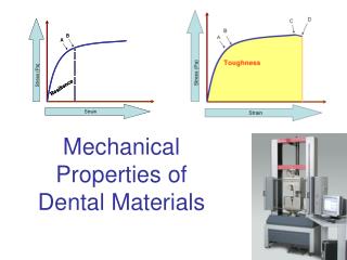
Tension • Stress-strain curves • Linear elastic: elongation in the specimen that is proportional to the applied load. • Engineering stress: the ratio of the applied load P, to the original cross-sectional area, Ao, of the specimen. • Engineering stress equation: σ = P/Ao • Engineering strain equation: e = (l-lo)/lo
Tension • Yield Stress: the stress at which permanent (plastic) deformation occurs. • Permanent (plastic) deformation: stress and strain are no longer proportional. • Ultimate tensile strength (UTS): the maximum engineering stress.
Tension • If the specimen is loaded beyond its UTS it begins to “neck.” • Fracture stress: the engineering stress at fracture.
Tension • Modulus of elasticity: ration of stress to strain in the elastic region. • Modulus of elasticity equation: E = σ/e • This linear relationship is known as Hooke’s Law. • Poisons Ratio: the ratio of the lateral strain to the longitudinal strain.
Ductility • Ductility: extent of plastic deformation that the material undergoes before fracture. • Two measures of ductility: • Total elongation: (lf-lo)/lo x 100% • Reduction of Area: (Ao-Af)/Ao x 100%
True-Stress and True-Strain • True-stress: ratio of the load, P, to the instantaneous cross-sectional area, A, of the specimen. • True-strain: the sum of all the instantaneous engineering strains. • True-stress equation: σ = P/A • True-strain equation: e = ln(l/lo)
Construction of Stress-Strain Curves • The stress-strain curve can be represented by the equation: σ = Ken • K = strength coefficient • n = strain hardening exponent • Specific energy: energy-per-unit volume of the material deformed.
Strain at Necking in a Tension Test • True-strain at necking is equal numerically to the strain-hardening exponent, n, of the material.
Temperature Effects • As temperature increases: • Ductility and toughness increase. • Yield stress and the modulus of elasticity decrease. • Temperature also affects the strain-hardening exponent of most metals, in that n decreases as temperature increases.
Section 2.2.7 – 2.7 • Rate of Deformation • Superplasticity • Effects of Compression, Torsion, and Bending • Hardness, Toughness, and Strength
Rate of Deformation Effects • Some machines form materials at low speeds. • Hydraulic Presses • Some Machines form materials at high speeds. • Mechanical Presses
Rate of Deformation Effects • Deformation rate: the speed at which a tension test is being carried out, in units of m/s or ft/min. • Strain rate: a function of the specimen length. • Short specimens stretch more during the same time period than a long specimen would.
Effects of Temp and Strain • Typical effects that temperature and strain rate have together on the strength of metals: • Sensitivity of strength-to-strain rate increases with temperature. • Increasing the strain rate increases the strength of the material (strain-rate hardening). • The slope of these curves is called the strain-rate sensitivity exponent. • The relationship between strength and strain is represented by: = Cem • C is the strength coefficient and e is the true strain rate. m is the slope of the graph.
Rate of Deformation Effects • Ex: You have 2 rubber bands, one 20 mm and the other 100mm in length. You elongate them both by 10mm in a period of 1 sec. The engineering strain in the shorter one is 10/20=.5 while the longer one is 10/100=.1, thus the strain rates are .5 s-1 and .1 s-1
Superplasticity • Refers to the capability of some materials to undergo large, uniform elongation prior to necking and fracture. • This elongation can be as long as 200% to 2000% of the original length. • Common items that demonstrate this: bubble gum, glass (at high temp) and thermo plastics. • Because of this capability, some materials can be formed into complex shapes such as beverage bottles and even neon advertisement signs.
Other Deformation Effects • Hydrostatic Pressure: pressure due to weight of a fluid. • Exposing some types of metals to high radiation is known to increase yield stress, tensile strength, and hardness. However it decreases ductility and toughness. • Increasing hydrostatic pressure can increase the strain at fracture of materials. • Billet: A semi-finished form of steel that is used for long products such as bars and channels. • Creating hydrostatic pressure on a billet can turn 1 m of billet into 14 km of wire.
Compression • Many operations in manufacturing, especially with forging, rolling, and extrusion, are performed with the material being subjected to compressive forces.
Compression Test • A specimen is subjected to a compressive load. • Carried out by compressing a solid cylindrical specimen between two well-lubricated flat dies. • The cylindrical specimen’s surface begins to bulge, known as barreling.
Disk Test • Compression test developed for brittle materials such as ceramics and glass. • A disk shaped specimen is loaded between to solid platens. Tensile stresses build up perpendicular to the centerline along the disk, fracture begins, and the disk will split vertically. • Tensile stress from this test can be calculated with the following equation: = 2P/dt P is load at fracture, d is diameter of disk, t is thickness.
Torsion Test • In addition to tension and compression, a work-piece may be subjected to shear strains. • Punching holes in sheet metal. • Metal cutting. • Torsion test used for determination of properties in “shear.” Usually performed on a thin tubular specimen. • Shear stress can be calculated with formula: T/2r2t • T is torque, r is average radius of tube, t is thickness of tube. • Shear strain is calculated with formula: rФ/l • r is radius of tube, Ф is angle of twist in radians, and l is length of tube.
Torsion Test • The ratio of the shear stress to the shear strain in the elastic range is known as the shear modulus or modulus of rigidity. • The angle of twist, Ф, to fracture in the torsion of solid round bars and elevated temp can help estimate forge-ability of metals.
Bending • Preparing specimens from brittle materials, such as ceramics and carbides, is difficult because of problems in shaping and machining them to certain dimensions. • The most common test for brittle materials is the bend or flexure test.
Bend / Flexure Test • Rectangular specimen supported at its ends. • Load is applied vertically at 1 or 2 pts. • The stress at fracture in bending is known as the modulus of rupture, flexural strength, or transverse rupture strength.
Hardness • Commonly used property which gives indication of the strength and resistance to scratch and wear of a material/specimen. • Resistance to permanent indentation. • Hardness is not a fundamental property because indentation depends on shape of indenter and load applied.
Brinell Test • J. A. Brinell 1900 • Involves pressing a steel or carbide ball of 10mm against a surface with various loads. • 500, 1500, or 3000 kg • Measures diameter of indentation. • Harder surfaces have small indentation while softer surfaces have larger indentation.
Rockwell Test • S. P. Rockwell 1922 • Test measures depth rather than diameter of indentation. • Diamond indenter presses against surface with minor load and then major load. • The difference in depths of penetration is a measure of the hardness of material.
Vickers Test • Developed in 1922. • Comparable to Brinell Test except using a pyramid shaped diamond to make indentation. • Lighter loads than Brinell Test • From 1 to 120 kg
Knoop Test • Developed in 1939. • Comparable to Brinell and Vickers test. • Uses an elongated pyramid shaped diamond to make indentations. • Uses very light loads. • From 25 g to 5 kg. • Known as a micro-hardness test because of the lights loads. • Suitable for very small or very thin specimens. • Test also used for measuring the hardness of individual grains and components in a metal alloy.
Mohs Hardness Test • Developed by F. Mohs in 1822. • Test based on capability of one material to scratch another. • Each material can scratch all materials below it with a lesser hardness. • Based on a scale of 1 to 10.
Scleroscope • Instrument with diamond-tipped hammer. • Hammer is dropped from a certain height. • Hardness is related to the rebound of the indenter. • Small and portable.
Durometer • Used to test hardness of plastics, rubbers, and other soft materials. • An indenter is pressed against the surface and then a constant load is applied rapidly. • Hardness is measured based on depth of indent after 1 second.
Fatigue • Fatigue – Components in manufacturing equipment are subjected to fluctuating cyclic (periodic) loads and static loads. • Cyclic Stress – on gear teeth • Thermal Stress -- cool die in repeated contact with hot work pieces • Both stresses may cause part failure at stress levels below normal static stress loading
Fatigue • Fatigue Failure -- Failure associated with every stress cycle, propagated through the material until critical crack is reached and material fractures. • Fatigue Testing -- Various stresses, tension then bending to a maximum load limit (total failure.)
Fatigue • S-N Curves • Stress Amplitude (S) -- Maximum stress specimen is subjected • Number of Cycles (N) • Level of stress a material tolerates decreases with an increase in cycles.
Fatigue • Endurance (Fatigue Limit) -- Maximum stress material may be subjected without fatigue failure. • Aluminum Alloys and similar materials exhibit an indefinite endurance limit. • Fatigue strength is specified at a certain number of cycles (10^7.) • Carbon Steels have a proportional endurance limit and tensile strength, usually 0.4 to 0.5.
Creep • Permanent elongation of a component under a static load maintained for a period of time. • Grain-Boundary Sliding -- Mechanism of creep at an elevated temperature in metals. • In high-temperature applications, gas-turbine blades, jet engines, and rocket motors. • May occur in tools and dies subjected to constant elevated temperatures (forging and extrusion.)
Creep • Creep Testing -- Subjecting a specimen to a constant tensile load (engineering stress) at a certain temperature, measuring the length changes at various time increments. • Primary, secondary, and tertiary stages
Creep • Rupture (Creep Rupture) -- Failure by necking and fractures • Creep rate increases with specimen temperature and the applied load. • Secondary Linear ranges and slopes aid to determine reliable design. • A higher melting point generally is related to an increase in creep resistance. • Stainless Steels, Super-alloys and Refractory metals and alloys
Creep • Stress Relaxation -- The stresses resulting from loading of a structural component decrease in magnitude over a period of time, while the dimensions of the component remain constant. • Thermoplastics
Impact • Testing consists of placing a notched specimen in an impact tester and breaking it with a swinging pendulum. • Impact or Dynamic Loading • CharpyTest -- Specimen supported at both ends. • Izod Test -- Specimen supported at one end.
Impact • Impact Toughness -- The energy dissipated in breaking the specimen may be obtained from the amount of swing in the pendulum. • Useful in determining the ductile-brittle transition temperature of materials. • High Impact Resistance – High Strength – High Ductility – High Toughness
Impact • Notch Sensitivity -- Sensitivities to surface defects, lowers impact toughness. • Heat-treated metals, Ceramics, and Glasses
Failure and Fracture of Material • Failure -- One of the most important aspects of material behavior. It directly influences the selection of a material for a particular application, the methods of manufacturing, and the service life of the component.