Download
1 / 31
330 likes | 508 Vues
Applications of the Global Positioning System. Prof. Thomas Herring Department of Earth, Atmosphere and Planetary Sciences 12.080 Seminar Fall 2004 . http://geoweb.mit.edu/~tah tah@mit.edu. Overview. Briefly review history of GPS: original aims of few-meter positioning

E N D
Applications of the Global Positioning System Prof. Thomas Herring Department of Earth, Atmosphere and Planetary Sciences 12.080 Seminar Fall 2004. http://geoweb.mit.edu/~tah tah@mit.edu
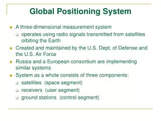
Overview • Briefly review history of GPS: original aims of few-meter positioning • Examine some MIT projects where GPS is used to make sub-millimeter position measurements and study deformation processes. • New Zealand • Oil field deformation • North America Plate deformation 12.080 GPS
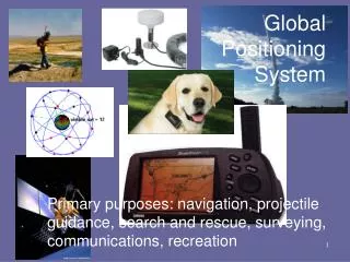
GPS Original Design (circa 1970) • Started development in the late 1960s as NAVY/USAF project to replace Doppler positioning system • Aim: Real-time positioning to < 10 meters, capable of being used on fast moving vehicles. • Limit civilian (“non-authorized”) users to 100 meter positioning. 12.080 GPS
GPS Design • Innovations: • Use multiple satellites (originally 21, now ~28) • All satellites transmit at same frequency • Signals encoded with unique “bi-phase, quadrature code” generated by pseudo-random sequence (designated by PRN, PR number): Spread-spectrum transmission. • Dual frequency band transmission (allows propagation delay due to the ionosphere to be removed): • L1 ~1.5 GHz, L2 ~1.25 GHz • Use of phase measurements allows millimeter level position determinations 12.080 GPS
Latest Block IIR satellite(1,100 kg) • Total system cost is over $10B • Average cost per satellite is ~$60M • None of these costs are passed directly to users. • Satellites transmit signals that any one with the correct receivers can use (no use tax on receivers) 12.080 GPS
Measurements • Measurements: • Time difference between signal transmission from satellite and its arrival at ground station (called “pseudo-range”, precise to 0.1–10 m) • Carrier phase difference between transmitter and receiver (precise to a few millimeters) • Doppler shift of received signal • All measurements relative to “clocks” in ground receiver and satellites (but use of multiple satellites and receivers allow this problem to be removed). • High precision, dual frequency receivers now $4000-$6000 12.080 GPS
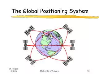
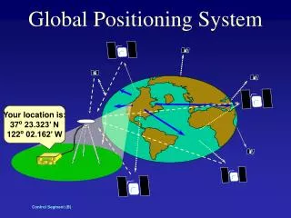
Satellite constellation • Since multiple satellites need to be seen at same time (four or more): • Many satellites (original 21 but now 28) • High altitude so that large portion of Earth can be seen (20,000 km altitude —MEO) 12.080 GPS
Current constellation • Relative sizes correct (inertial space view) • “Fuzzy” lines not due to orbit perturbations, but due to satellites being in 6-planes at 55o inclination. 12.080 GPS
Some MIT projects using GPS • The MIT Geodesy and Geodynamics group (http://geoweb.mit.edu) is involved in many projects around the world with using GPS. • Three projects to discuss (all involving measurement of height changes) • Uplift in New Zealand Southern Alps • Subsidence in oil fields • Uplift and subsidence across North America (response to last ice-age: Glacial Isostatic Adjustment GIA) • All these projects involve collaborations with other groups. 12.080 GPS
A Direct Geodetic Measurement of the Uplift Rate of the Southern Alps John Beavan1 Mikael Denham2 Paul Denys2 Brad Hager3 Tom Herring3 Chuck Kurnik4 Dion Matheson1 Peter Molnar5 Chris Pearson2 1 GNS 2 Otago University 3 MIT 4 UNAVCO 5 Univ. Colorado 12.080 GPS
New ZealandTectonic and bathymetricsetting Central South Island experiences oblique continental collision at about 40 mm/yr Shortening component normal to Alpine fault is about 10 mm/yr 12.080 GPS Image from NIWA National Institute of Water and Atmospheric Research Ltd
SAGENZ Profile: Karangarua to Lake Tekapo Southern Alps Geodetic Experiment - New Zealand Australian Plate QUAR MTJO Christchurch 40 mm/yr Pacific Plate 12.080 GPS Image courtesy of Earth Sciences and Image Analysis Laboratory, NASA Johnson Space Center
OCCUPATION STRATEGY for CONTINUOUS and SEMI-CONTINUOUS GPS STATIONS • Permanent ground marks at all sites, with force-centered antenna mounts • Five sites occupied continuously, with data transmitted by radio modem and dial-up internet • Six other sites occupied semi-continuously by rotating 3 receivers between the sites every 3 months • 60-second sampling used to enable 3 months of data to be stored in internal memory • Same antennas used at each site during each occupation 12.080 GPS
A Southern Alps semi-continuous GPS station 12.080 GPS
Sometimes we have to find the sites 12.080 GPS
And test snow integrity 12.080 GPS
SAGENZ GPS STATIONS SE NW VEXA WAKA MTJO QUAR PILK NETT Alpine Fault KARA REDD LEOC MAKA CNCL Continuous station Semi-continuous 12.080 GPS Image courtesy of Earth Sciences and Image Analysis Laboratory, NASA Johnson Space Center
Vertical position time series after filtering to remove annual signals and common-mode noise • RMS about a straight line fit is typically 2.5 - 4 mm. Worst case (NETT) is 6.5 mm. 12.080 GPS
Measured uplift rates and 95% confidence 12.080 GPS
For a complete change in climate: Oil field monitoring in Oman.Summer daytime temperatures of 50C (120F) 12.080 GPS
Basic GPS setup Site at the suspected center of the subsidence 12.080 GPS
Drilled-braced monument Continuous GPS site (5 of these) Telemetry antenna Passive cooled equipment box Solar panel GPS Monument and antenna 12.080 GPS
355 mm Pillar is ~3 meters deep Rover GPS sites (45 of these) 12.080 GPS
Time series of height estimates in the center of the field Error bars scaled based on “global” GPS analysis Two analysesshown that treatatmospheric delay differently Receiver failure and repair 12.080 GPS
Horizontalmotion at REM3 Note: if the sitewere truly at the center of the subsidence, no horizontal motion would be expected Some non-steady motion can be seen 12.080 GPS
Deformation from 9-months GPS 12.080 GPS
Postglacial rebound in North America • Here is combine temporal changes in position estimates from ~300 sites across North America. • These results are generated by many different groups and need to be carefully evaluated. • The results from the best sites are used to infer which GIA models best match the measurements. (Depends on structure of the Earth) 12.080 GPS
Fit of COD to GIA: 9/1995-3/2004: 17 sites This minimummoves with increasing LT Details here depend geographic sites distribution Lithosphere Thickness (LT) 71 km 12.080 GPS
Comparison of PUR solution (red, 50% confidence ellipses) with GIA model 71 km LT, UM 1, LM 2x10²¹ Pa-s Fit: 26-sitesN 0.6 mm/yrE 0.3 mm/yrU 1.9 mm/yr 12.080 GPS
Conclusions • GPS dual-use technology: Applications in civilian world widespread • Geophysical studies (mm accuracy) • Engineering positioning (<cm in real-time) • Commercial positioning: cars, aircraft, boats (cm to m level in real-time) • MIT has projects using GPS in many parts of the world studying a variety of problems • Plate Boundary Observatory will be a major project over the next 10 years in the US 12.080 GPS