Download
1 / 15
150 likes | 327 Vues
Introducing the Specifications of the Metro Ethernet Forum. MEF 18 Abstract Test Suite for Circuit Emulation Services over Ethernet based on MEF 8. February 2008. Introducing the Specifications of the Metro Ethernet Forum. MEF 2 Requirements and Framework for Ethernet Service Protection

E N D
Introducing the Specifications of the Metro Ethernet Forum MEF 18 Abstract Test Suite for Circuit Emulation Services over Ethernet based on MEF 8 February 2008
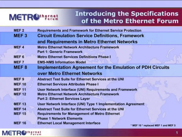
Introducing the Specifications of the Metro Ethernet Forum • MEF 2 Requirements and Framework for Ethernet Service Protection • MEF 3 Circuit Emulation Service Definitions, Framework and Requirements in Metro Ethernet Networks • MEF 4 Metro Ethernet Network Architecture Framework Part 1: Generic Framework • MEF 6 Metro Ethernet Services Definitions Phase I • MEF 7 EMS-NMS Information Model • MEF 8 Implementation Agreement for the Emulation of PDH Circuits over Metro Ethernet Networks • MEF 9 Abstract Test Suite for Ethernet Services at the UNI • MEF 10.1 Ethernet Services Attributes Phase 2* • MEF 11 User Network Interface (UNI) Requirements and Framework • MEF 12 Metro Ethernet Network Architecture Framework Part 2: Ethernet Services Layer • MEF 13 User Network Interface (UNI) Type 1 Implementation Agreement • MEF 14 Abstract Test Suite for Traffic Management Phase 1 • MEF 15 Requirements for Management of Metro Ethernet Phase 1 Network Elements • MEF 16 Ethernet Local Management Interface • MEF 17 Service OAM Framework and Requirements • MEF 18 Abstract Test Suite for Circuit Emulation Services • MEF 19 Abstract Test Suite for UNI Type 1 * MEF 10 .1 replaces and enhances MEF 10 Ethernet Services Definition Phase 1 and replaced MEF 1 and MEF 5.
This Presentation • Purpose: • This presentation is an introduction to MEF 18 • MEF 17 defines requirements and a framework for service Operations, Administration and Maintenance (OAM) within MEF compliant Metro Ethernet Networks (MEN). • Audience • Equipment Manufacturers building devices that will carry Carrier Ethernet Services. • Useful for Service Providers architecting their systems • Other Documents • Presentations of the other specifications and an overview of all specifications is available on the MEF web site • Other materials such as white papers and case studies are also available
MEF 18 Abstract Test Suite for CES Purpose Specifies testing procedures for pass/fail assessment of conformance with each of the operating modes in MEF 8. Audience Equipment Manufacturers building devices that will carry TDM traffic across Carrier Ethernet Networks. Useful for Service Providers architecting their systems. Technical Committee Test and Measurement Area
MEF 3 Circuit Emulation Service Definitions, Framework and Requirements in Metro Ethernet Networks Purpose Circuit Emulation Service “tunnels” TDM traffic through a Metro Ethernet network allowing inclusion of legacy networks within a Carrier Ethernet environment Audience Equipment Manufacturers supporting devices that provide Circuit Emulation over Carrier Ethernet Services.Useful for Service Providers architecting their systems. Technical Committee Service Area MEF 8 Implementation Agreement for the Emulation of PDH Circuits over Metro Ethernet Networks Purpose Gives precise instructions for implementing interoperable CES equipment that reliably transport TDM circuits across Metro Ethernet Networks while meeting the required performance of circuit emulated TDM services as defined in ITU-T and ANSI TDM standards Audience Equipment Manufacturers supporting devices that provide Circuit Emulation over Carrier Ethernet Services.Useful for Service Providers architecting their systems. Technical Committee Service Area
MEF 8 describes several operating modes for the implementation of CESoETH. Figure 5‑1 shows these modes using a tree diagram (section numbers given are from MEF 8). Only one mode is mandatory to claim conformance with MEF 8, structure-agnostic emulation using a raw (i.e. non-octet-aligned) encapsulation. Several optional operating modes are described in MEF 8, e.g. structure-aware emulation modes, and different signaling types. • Within each operating mode, a number of requirements are defined. Some of these requirements are mandatory (as indicated by the key words “MUST” or “SHALL”), and some are optional (as indicated by the key words “SHOULD”, “MAY” or “OPTIONAL”). There are three categories of requirements for MEF8 compliance: • Mandatory – the mandatory requirements for the mandatory structure-agnostic emulation mode. These requirements must be met to claim MEF 8 conformance. • Dependent – the mandatory requirements for the optional modes. These requirements must be met to claim MEF 8 conformance for those optional modes (i.e. their status is dependent on whether the relevant operating mode is supported). • Optional – these requirements describe permitted options. These requirements do not have to be met to claim MEF 8 conformance. • Table 8-1 in section 8 lists each of the MEF 8 requirements, together with its category and the reference of the test used to verify it. This specification defines tests for all the mandatory requirements in section 6, and dependent requirements in section 7.
Generic Test Beds • The majority of tests will use one of the two following generic test beds. Some tests will require extra facilities, and these are described alongside the relevant tests. Note that the device under test may be provided by multiple pieces of equipment, provided the necessary functions and interfaces are provided.
Test Bed 1 • The first generic test bed consists of equipment for generating and receiving TDM services (e.g. DS1, E1, DS3 or E3 circuits), the device under test, equipment for examining the content of Ethernet frames, and equipment for generating Ethernet frames with specific contents. The device under test is controlled by a management station. This is connected to the device via a management interface. The nature of this interface will be specific to the device under test.
Test Bed 1 • The generic test procedure will be to set up the device under test and the test equipment, then either: • Generate a TDM circuit using the TDM generator, and apply to the device under test. Examine the contents of the resulting Ethernet frames containing the TDM data using the Ethernet frame analyser. Verify that the format and contents are correct. If relevant to the particular test, use the management station to verify that the correct alarms have been reported, and that the statistics recorded are correct. • Generate a stream of Ethernet frames using the frame generator, and apply to the device under test. Examine the resulting TDM stream using the TDM analyzer. Verify that the format and contents are correct. If relevant to the particular test, use the management station to verify that the correct alarms have been reported, and that the statistics recorded are correct.
Test Bed 2 • The second generic test bed consists of equipment for generating and receiving TDM services (e.g. DS1, E1, DS3 or E3 circuits), two identical devices to be tested, and equipment representing an Ethernet network. The devices under test are controlled by a management station, connected via a management interface. The nature of this interface will be specific to the device under test.
Test Bed 2 • The generic test procedure will be to set up the devices under test and the test equipment, and then generate a TDM circuit using the TDM generator, and apply to the first device under test. Ethernet frames generated by this device are passed through the emulated network to the second device under test. This recreates the TDM stream, which is passed to a TDM tester for analysis. In practice, the two TDM testers shown may actually be the same device, facilitating error checking of the data or measurements such as end-to-end TDM latency. • Note that the function and nature of the emulated network may vary according to the test being conducted. For example, in test case 6 it takes the form of an actual network of Ethernet switches (as described in Appendix VI of G.8261). In many of the tests, the emulated network simply needs to have the capability to act as an Ethernet “sniffer”, monitoring the contents of the stream of Ethernet frames flowing between the two DUTs without modifying or impairing the stream. Lastly, some tests also require the ability to impair the stream in the following ways, and these tests may require a “network emulator” box: • Delay frames by a variable amount • Delete frames • Re-order frames • Duplicate frames • Insert spurious frames • Insert data errors • The descriptions of each test describe how the emulated network should be configured and behave for the correct operation of the test.
Test Summary – 17 Test Cases TESTS FOR MANDATORY REQUIREMENTS • Encapsulation Layers • Emulated Circuit Identifier and Frame Sequencing • CESoETH control word • Payload Format • Structure Agnostic Emulation • Synchronisation • Defects, Performance Monitoring and Management • Misconnection • Late Arriving Frames • Jitter Buffer Overrun and Underrun Defects TESTS FOR DEPENDENT REQUIREMENTS • Tests for Octet Aligned Payload of DS1 Circuits • Tests for Structure-Locked Encapsulation • Tests for Structure-Indicated Encapsulation • TDM Application Signaling • CE Signaling Frames • Channel associated Signaling (CAS) Frames
For Full Details … Please visit www.metroethernetforum.org to access the full specification E-Line Service type Point-to-Point EVC UNI UNI CE E-LAN Service type CE Carrier Ethernet Network CE UNI Carrier Ethernet Network UNI Multipoint-to-Multipoint EVC CE MEF certified Carrier Ethernet products UNI: User Network Interface, CE: Customer Equipment
Accelerating Worldwide Adoption of Carrier-class Ethernet Networks and Services www.MetroEthernetForum.org