Download

1 / 19
190 likes | 310 Vues
DC-Readout for GEO. Stefan Hild for the GEO-team. Heterodyne vs DC-readout. It is a noteworthy fact, that in recent times the relative stability of the light in the IFO is better than the relative phase noise achievable with excellent RF technique.

E N D
DC-Readout for GEO Stefan Hild for the GEO-team
Heterodyne vs DC-readout It is a noteworthy fact, that in recent times the relative stability of the light in the IFO is better than the relative phase noise achievable with excellent RF technique. • Local oscillator for heterodyne: RF sidebands (Schnupp modulation). • Local oscillator for DC-readout: Carrier light from dark fringe offset.
Motivation: win at high frequencies • Limits at high frequencies: • shot noise • darknoise of main photodiode (+mixer) • oscillator phase noise
Shot noise improvement from DC_readout When going to DC-readout the signal to shotnoise ratio will be increased by a factor between sqrt(1.5) for balanced sidebands and sqrt(2) for completely unbalanced sidebands. Measurements of the dark port light field of GEO (TEM00) using a scanning Fabry-Perot cavity. We expect an increase roughly in the middle between balanced and unbalanced.
Dark noise • Requirements for the main photodiode: • high dynamical range • capable of RF signals • Limited by electronic noise of the photocurrent2voltage stage and the first amplifing OP. Will be gone when only DC signals have to be detected.
Oscillator phase noise Usually considered as technical noise. However at the current sensitivity levels it is a serious problem. Will be gone when going to DC-readout !!
First step towards DC-readout (1) We see already the MI differential calibration lines in the DC power at the dark port (10 times less sensitive than the GW channel)
Simulated Shotnoise for S5, homo vs hetero DC readout, dark fringe = no dark fringe offset, mindex = S5 nominal Simulated shot noise for S5 (550Hz)
First step towards DC-readout (2) Measurement of the amplitude ratio of GW-like events in H and MID_VIS. Around 1.8 kHz MID_VIS is especially sensitive to GW-like signals.
First step towards DC-readout (2) • 1st IDEA • demonstration gain sensitivity at high frequency (few kHz): • Leave the detector control mainly as it is at the moment (still use Schnupp modulation and use error signals derived from RF). • (MI_long + MI_AA from MI_quad_PD) • Introduce an offset from dark fringe. • Add a output mode cleaner in air in the HPD path (aiming for reducing the MI sidebands by a factor of 10 = pole at 1.5MHz). • That will give poor sensitivity at low frequencies, but there is a chance to confirm the gain in sensitivity at high frequencies.
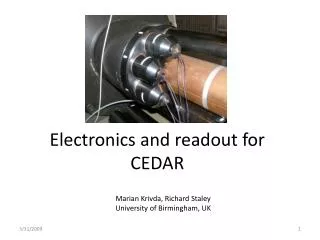
Optical Layout of the GEO detection bench • Currently: • PDOQ used for MID_AA + MID_long lock (acquistion) • HPD used for MID_long lock in final config.+ readout in final config. • DC-readout • PDOQ used for MID_AA + MID_long lock (acquistion + final) • HPD used for MID_long readout in final config.
Current noise performance PDOQ used for locking signal. Readout with HPD. Above 1.5 kHz roughly the same sensitivity is achieved (can probably be further improved)
Determine the optimal dark fringe offset Optimal offset: 0.036 deg (diff) => 104 pm Nearly optimal already: 0.018 deg (diff) => 52 pm
The MI long. errorsignal Using an errorsignal derived from heterodyne readout, locking should be easy. Proposed offset = 0.018 deg Locking range 5 to 10 times larger.
Sensitivity for DC-readout • For this simulation the MI mod_index was reduced to 5% of nominal S5: • A factor of reduction from decreasing the applied mod index. • A factor of 10 from filtering at the output modecleaner
Simulated power noise coupling • Compared the power noise coupling to the GW-channel for 1pm df-offset and 50 pm df-offset. • For 1 pm df-offset the power noise coupling is dominated not by the dark fringe offset but by higher order mode contribution • The increase of power noise coupling originating from the dark fringe offset of 50 pm is roughly 45.
How to go on in terms of simulations • Simulate light power present on the dark port diodes. • Design of a proper output mode cleaner • Simulate beam jitter requirements for OMC • Simulate and find a locking signal for using only the homodyne signal. Insatllation and commissiong of the output mode cleaner. Checking sensitivity. - If no reasonable sensitivity can be achieved stopp DC-readout efforts !! - If a reasonable sensitivity can be achieved go on:
Acquisition of Dual Recycling 9.01...MHz 14.905MHz