Download
1 / 35
350 likes | 563 Vues
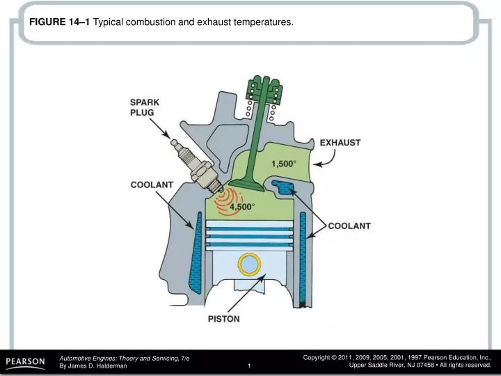
FIGURE 14–1 Typical combustion and exhaust temperatures. FIGURE 14–2 Coolant circulates through the water jackets in the engine block and cylinder head. FIGURE 14–3 Coolant flow through a typical engine cooling system.

E N D
FIGURE 14–2 Coolant circulates through the water jackets in the engine block and cylinder head.
FIGURE 14–3 Coolant flow through a typical engine cooling system.
FIGURE 14–4 A cross section of a typical wax-actuated thermostat showing the position of the wax pellet and spring.
FIGURE 14–5 (a) When the engine is cold, the coolant flows through the bypass. (b) When the thermostat opens, the coolant can flow to the radiator.
FIGURE 14–6 A thermostat stuck in the open position caused the engine to operate too cold. If a thermostat is stuck closed, this can cause the engine to overheat.
FIGURE 14–7 This internal bypass passage in the thermostat housing directs cold coolant to the water pump.
FIGURE 14–8 A cutaway of a small block Chevrolet V-8 showing the passage from the cylinder head through the front of the intake manifold to the thermostat.
FIGURE 14–9 Checking the opening temperature of a thermostat.
FIGURE 14–10 Some thermostats are an integral part of the housing. This thermostat and radiator hose housing is serviced as an assembly. Some thermostats snap into the engine radiator fill tube underneath the pressure cap.
FIGURE 14–12 A radiator may be either a down-flow or a cross-flow type.
FIGURE 14–13 Many vehicles equipped with an automatic transmission use a transmission fluid cooler installed in one of the radiator tanks.
FIGURE 14–14 The pressure valve maintains the system pressure and allows excess pressure to vent. The vacuum valve allows coolant to return to the system from the recovery tank.
FIGURE 14–15 The level in the coolant recovery system raises and lowers with engine temperature.
FIGURE 14–16 Some vehicles use a surge tank, which is located at the highest level of the cooling system, with a radiator cap.
FIGURE 14–17 Coolant flow through the impeller and scroll of a coolant pump for a V-type engine.
FIGURE 14–18 A demonstration engine running on a stand, showing the amount of coolant flow that actually occurs through the cooling system.
FIGURE 14–19 This severely corroded water pump could not circulate enough coolant to keep the engine cool. As a result, the engine overheated and blew a head gasket.
FIGURE 14–20 The bleed weep hole in the water pump allows coolant to leak out of the pump and not be forced into the bearing. If the bearing failed, more serious damage could result.
FIGURE 14–21 A cutaway of a typical water pump showing the long bearing assembly and the seal. The weep hole is located between the seal and the bearing. If the seal fails, then coolant flows out of the weep hole to prevent the coolant from damaging the bearing.
FIGURE 14–22 A Chevrolet V-8 block that shows the large coolant holes and the smaller gas vent or bleed holes that must match the head gasket when the engine is assembled.
FIGURE 14–23 A typical electric cooling fan assembly showing the radiator and related components.
FIGURE 14–24 A typical engine-driven thermostatic spring cooling fan.
FIGURE 14–25 A typical heater core installed in a heating, ventilation, and air-conditioning (HVAC) housing assembly.
FIGURE 14–26 A heavily corroded radiator from a vehicle that was overheating. A visual inspection discovered that the corrosion had eaten away many of the cooling fins, yet did not leak. This radiator was replaced and it solved the overheating problem.
FIGURE 14–27 Pressure testing the cooling system. A typical hand-operated pressure tester applies pressure equal to the radiator cap pressure. The pressure should hold; if it drops, this indicates a leak somewhere in the cooling system. An adapter is used to attach the pump to the cap to determine if the radiator can hold pressure, and release it when pressure rises above its maximum rated pressure setting.
FIGURE 14–28 The pressure cap should be checked for proper operation using a pressure tester as part of the cooling system diagnosis.
FIGURE 14–29 Use dye specifically made for coolant when checking for leaks using a black light.
FIGURE 14–30 When an engine overheats, often the coolant overflow container boils.
FIGURE 14–31 Typical marks on an accessory drive belt tensioner.
FIGURE 14–32 (a) Many vehicle manufacturers recommend that the bleeder valve be opened whenever refilling the cooling system. (b) Chrysler recommends that a clear plastic hose (1/4 in. ID) be attached to the bleeder valve and directed into a suitable container to keep from spilling coolant onto the ground and on the engine and to allow the technician to observe the flow of coolant for any remaining oil bubbles.
FIGURE 14–33 Using a coolant exchange machine helps eliminate the problem of air getting into the system which can cause overheating or lack of heat due to air pockets getting trapped in the system.
FIGURE 14–34 All cooling system hoses should be checked for wear or damage.
FIGURE 14–35 The top 3/8 in. hose is designed for oil and similar liquids, whereas the 3/8 in. hose below is labeled “heater hose” and is designed for coolant.