Download
1 / 26
260 likes | 374 Vues
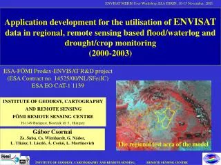
Radar Interferometry. Prof. Arnon Karnieli The Remote Sensing Laboratory Jacob Blaustein Institute for Desert Research Ben-Gurion University of the Negev Sede-Boker Campus 84990, ISRAEL. Radar Interferometry.

E N D
Radar Interferometry Prof. Arnon Karnieli The Remote Sensing Laboratory Jacob Blaustein Institute for Desert Research Ben-Gurion University of the Negev Sede-Boker Campus 84990, ISRAEL
Radar Interferometry • Based on two images requisition of the same zone from slight different orbits of the satellite. • The two phase values at each pixel are subtracted, leading to an interferogram that records only the differences in phase between the two original images. • Analogous to the use of lasers for making holograms
Phase Phase of a wave refers to its starting point relative to some arbitrary time zero, expressed in degree.
Phase Schematic representation of phase in sine waves; t = time; waves 'A' and 'B' are 90° out-of-phase; waves 'A' and 'C' are in-phase.
Separation by adjacent orbit (e.g. ERS) Baseline ~ 600 m Repeat orbit ~ 3 days
Radar SimpleInterferometry Separation of two antennas in space, creating a baseline to map surface topography with great precision (3-30 m accuracy). Iso-displacement curves
Radar SimpleInterferometry This enables rapid production of Digital Elevation Models (DEMs)
Radar Differential Interferometry • Based on two SAR images, which create a simple interferometry and a third one, separated in time. Separation of two antennas in time, allowing before-and-after measurement of changes in land surface in cm accuracy. • Used for: • Map changes in topography over time; Volcanic swelling and subsidence; Seismic and pre-seismic motion; Glacier motion and stress; Swelling of clay soils due to moisture; Permafrost heaving due to freeze/thaw cycle; Dune movements.
Radar Differential Interferometry Ice sheet motion in Antarctica
Radar Differential Interferometry Image of deforestation in Amazonia
Differential Interpherogram model Izmit earthquake (August, 1999)
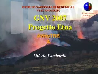
Radar Differential Interferometry Monitoring deformation of volcanoes; actual and modeled fringe patternsindicating subsidence of Mt Etna due to change of volume of magma chamber
Subsidences Over Paris “Integral” result over 2 years. 1Km 1.6 cm subsidence can be measured between Oct. 93 and July 95. Differential interferometry derived from ERS images. Subsidences are confirmed by ground truth. Louvre