Download
1 / 34
380 likes | 766 Vues
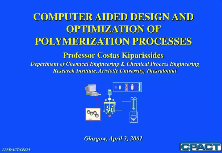
COMPUTER AIDED DESIGN AND OPTIMIZATION OF POLYMERIZATION PROCESSES. Professor Costas Kiparissides. Department of Chemical Engineering & Chemical Process Engineering Research Institute, Aristotle University, Thessaloniki. Glasgow, April 3, 2001. OUTLINE. Introduction

E N D
COMPUTER AIDED DESIGN AND OPTIMIZATION OF POLYMERIZATION PROCESSES Professor Costas Kiparissides Department of Chemical Engineering & Chemical Process Engineering Research Institute, Aristotle University, Thessaloniki Glasgow, April 3, 2001
OUTLINE • Introduction • Computer Aided Design of High Pressure Low Density PolyEthylene Tubular Reactors • Computer Aided Design of Industrial PVC Batch Suspension Polymerization Reactors • Computer Aided Design of Industrial Emulsion Polymerization Reactors • Computer Aided Design of Gas Phase Olefin Catalytic FBRs
CADOC of Polymerizations Reactors • In the Laboratory of Polymer Reaction Engineering at AUT/CPERI,computer-aided design (CAD), computer-aided process optimization and control(CADOC)are very actively promoted aiming at reactor design improvements, productivity increases, quality improvement, safer reactor operation, energy conservation, minimization of manufacturing waste and environmental impact, etc. • The philosophy adopted by LPRE is toward the development of custom-made CADOC software for specific polymerization processes. • The main problems to be addressed in the development of a CADOC software package are : • Deeper understanding of polymerization reactions (via mechanistic / data-based modelling and experimentation). • Ability to measure and characterize a whole range of polymer quality variables using a variety of hardware and software sensors. • Developmentof nonlinear model-based optimization and control policies with emphasis on achieving superior performance and constraint handling.
Key Ingredients of the Developed Software Packages • State-of-the-art model and physical properties evaluation. • Fusion of the modeling (academia) and operating (industry) expertise in order to: • consolidate the control and design objectives • identify the key reactor measurements and model parameters • structure the parameter estimation-control-optimization problems • Meticulous in their operations, transparent in their use.
Databases Features of the User-Friendly Interface • Menu driven - Problem Specific • Input Output • Automatically Created Formatted • Input - Output File • Database Aided Input • Graphics Output Input Files Editing Input Files Modified Input Files • Reactor Geometries and • Configurations, • Initiator Properties and • Mixtures FORTRANPrograms FORTRAN Output ' Processing Programs Output • Profiles of Temperature, • Pressure, • Heat Transf. Coefficient, • Weight - Number Av.M.W., • Density, Melt Index, • LCB, SCB, etc Reactor Temperature Comparative Graphs Graphs Formatted Printout
Comprehensive Reactor Model Measurements from the Reactor Adjustable Model Parameters Reactor Simulation Comprehensive Reactor Model + Fitted Parameters Estimation of Control Variables Control Objectives Estimation of Design Variables Design Objectives Functions of the Sofware Packages
COMPUTER AIDED DESIGNOF HIGH PRESSURE LOW DENSITY POLYETHYLENE TUBULAR REACTORS
LDPE Tubular Reactor Configuration • A tubular LDPE reactor consists of a spiral-wrapped metallic pipe with a large length-to-diameter ratio. The total length of the reactor ranges from 500 to 1500 m while its internal diameter does not exceed 60 mm. • The heat of reaction is partially removed through the reactor wall by water which flows through the reactor jacket. • The reactor is divided in to a number of sections in relation with process heat requirements and typically has multiple feedstreams and initiator mixture injection streams.
LDPE Modelling (Reactor Geometry Input) • Detailed input of reactor geometry (reactor sections, tubes and cross section information) • Input of reactor cooling systems information (information about coolant tanks, coolant flowrate and type of flow for each section)
LDPE Modelling (Input of Model Parameters) • Input of estimated model parameters (reactor section fouling factors, values initiator efficiency) • Input of kinetic parameters (Arrhenius factor, activation energy and activation volume for all elementary reactions of free radical polymerization)
LDPE Reactor Modelling (Graphics Output) • User-selected display of any two curves (e.g. number average molecular weight and polydispersity index of the final product) • Superposition of experimental data (e.g. temperature data)
LDPE Reactor Modelling (Graphics Output) • Comparison charts of any property between different reactor runs (e.g. overall heat transfer coefficient) • User-specified composite graphs (e.g. overall heat transfer, inside heat transfer and fouling heat transfer resistance)
COMPUTER AIDED DESIGNOF INDUSTRIAL PVC BATCH SUSPENSION POLYMERIZATION REACTORS
The Suspension Polymerization Prosess • Monomer dispersed as droplets (e.g. 20-250 μm). • Initiator dissolved in organic phase (monomer). • Dispersion maintained by agitation and addition of stabilizers (polymers, CMC, PVA, electrolytes). • Particle size distribution difficult to control. • Best for production of PS, PMMA, PVC, PVAc. • Final PSD in the range of 50-500 μm.
Kinetics: Reactor Modeling (GRAPHICS) • User-selected display of any two curves (e.g. VCM Conversion and Reactor Pressure) • Superposition of experimental data (e.g. VCM Conversion)
Particle Size Distribution (GRAPHICS) • Diameter Density Distribution evolution with time. • Volume Density Distribution evolution with time (log scale).
Morphology : DLA Simulations Evolution of PVC grain morphology up to 80% conversion for an actual industrial case. • Critical conversion xc=16%. • Final average porosity ε=11%. • Pore sizes range from 50nm to 5μm. (Length scale is in μm).
COMPUTER AIDED DESIGNOFINDUSTRIALEMULSION POLYMERIZATION REACTORS
Emulsion Polymerization Reactor Latex Particles Micelles Oligomers Monomer Droplet Precursors Modelling of Emulsion Polymerization Reaction Kinetics Thermodynamics of the emulsion mixture Aqueous phase radical concentration Diffusion-controlled termination and propagation reactions Homogeneous Rate of particle growth: Average number of radicals per particle Rate of radical entry Rate of particle formation: Nucleation mechanism Micellar Rate of radical exit Coagulative Radical termination Numerical methods for solving population balances Reactor Dynamics • Conversion • Particle number • Average particle radius • Molecular weight • Copolymer composition • PSD • MWD • CCD • DBD
Kinetics: Reactor Modeling (GRAPHICS) • Superposition of experimental data (e.g. Diameter of Swollen Particles)
Particle Size Distribution (GRAPHICS) • PredictedParticle Size Distributionat different conversions
COMPUTER AIDED DESIGNOF GAS PHASE OLEFIN CATALYTIC FBRs
Olefin Polymerization FBR: from reaction kinetics to FBR Modeling
Modeling of the Borstar® FBR Fluidized Bed Reactor Recirculation gas Catalyst Feed Product Polymer Removal Ethylene, Comonomer, H 2 Loop Reactor Make-up Feed Flash Separator
Dynamic Measurements from the Borstar® FBR 10 XC2mol 8 XH2mol XC4mol 6 Production rates (tn/h) FBR residence time (h) 4 Gas outlet GC measurement (% mol) 2 FBR production rate (energy balance) (C +C ) make-up feed rates 2 4 Loop production rate (energy balance) 0 0 20 40 60 80 100 120 140 160 180 200 220 240 time (h) 0 50 100 150 200 time (h)
Steady-state simulation of the Borstar® FBR • Steady-State predictions of the developed model were compared with the industrial dataThekinetic rate constantstheactive site fractionof the catalyst and thebed voidagewere considered as tuning parameters. Deviation of model predictions from industrial data Variable Error % Reactor Temperature 0.28 Production Rate 0.99 Residence Time 4.6 • The model predictions are in close agreement with the industrial data for two months of continuous operation of the reactor. Dynamic simulation of the Borstar® FBR • Dynamic model simulationswere performed and compared with the industrial data for 2 months of plant operation. The tuning parameters are kept constant with time. Dynamic simulations were performed using a numerical integration routine underFORTRANas well as thegPROMS®simulator.
Prediction of the Borstar® FBR PSD • The steady-statepopulation balance modelwas used for the prediction of theparticle size distributionof theBorstar®FBRover a wide variety of steady-states of different timeinstances of plant operation. The model predictions proved to be quite accurate (deviations in the order of magnitude of sampling and measurement errors). The reactor operating conditions corresponding tofour representative PSD measurements(denoted as SS1-4) are as follows:
Prediction of the Borstar® FBR PSD • Steady state 1 • Steady state 2
Prediction of the Borstar® FBR PSD • Steady state 4 • Steady state 3
Optimal Grade Transition in an FBR using gPROMS-gOPT Simulation-Optimization Package • An integral quadratic objective function is used as a performance index for this grade transition,penalizing the deviations of polymer’s MI and Densityfrom their desired values. • Hydrogen (FH2) and Comonomer (Fmon2) feed ratesare the only two manipulated variables required to achieve the desired polymer properties and they are used as optimization variables to carry out the grade transition. • The manipulated variable profile is discretized.The manipulated variables are expressed aspiecewise constant functionswhile the time domain is divided into a number ofdiscrete intervals. The optimal control problem is solved sequentially as an NLP. Therefore the optimizer must choose a set of parameters that construct the manipulated variable trajectories, in order to minimize the performance index shown above. • Theeffect of the discretization of the time domainon the grade transition is studied and the optimal policies are compared for different cases where the time domain is divided into 10/15/20 intervals equally spaced or not with tight or wider bounds for each interval.
Optimal Grade Transition in an FBR using gPROMS-gOPT Simulation-Optimization Package • Time domain is divided into 10/15/20non-equally spaced intervals.The transition under the optimum policy of the manipulated variables is compared with the transition under a simple step change of the manipulated variables.
CONCLUSIONS - PolyPROMS • An easy-to-use environment with a variety of interfaces including a fully interactive process flow diagram (PFD). • Capability to simulate a wide range of polymerization mechanisms and reaction media. • Full access to kinetic parameters, species properties/concentrations, process conditions. • Consistent thermodynamic modeling and data throughout. • A non-linear steady-state solver for the evaluation of steady states for interactively specified values of flowsheet parameters and the sensitivity analysis of the process output variables with respect to variations of model parameters. • General-purpose linear and non-linear programming algorithms for the off-line and on-line parameter and state estimation in polymerization process models. • General optimization tools for parametric steady-state optimization of a selected polymerization process. • Dynamic optimization methods for the determination of the time optimal control policies to improve product quality, maximize reactor throughput, or/and minimize the off-spec amount of polymer during a grade transition. • Non-linear model based predictive control (NMPC) algorithms for the feedback control of the polymerization processes.