Download
1 / 2
20 likes | 110 Vues
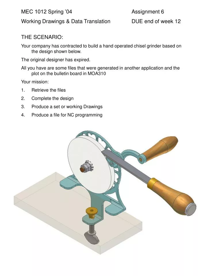
MEC 1012 Spring ’04 Assignment 6 Working Drawings & Data Translation DUE end of week 12. THE SCENARIO: Your company has contracted to build a hand operated chisel grinder based on the design shown below. The original designer has expired.

E N D
MEC 1012 Spring ’04 Assignment 6 Working Drawings & Data Translation DUE end of week 12 • THE SCENARIO: • Your company has contracted to build a hand operated chisel grinder based on the design shown below. • The original designer has expired. • All you have are some files that were generated in another application and the plot on the bulletin board in MOA310 • Your mission: • Retrieve the files • Complete the design • Produce a set or working Drawings • Produce a file for NC programming
DETAILS for Working Drawings and Data Translations • Make your .ipj in Assignment 6 • Copy the six files, located in the Assignment 6 COPY ME folder, to your Assignment 6 workgroup. • These files are .sat files that were generated in another application but you can import them into Inventor and use them. Similar to derived parts, you can add modifications to them but you will not be able to modify the features they were built with. • The Support Casting will need draft added as well as fillets. The parting line is planned to split following the line shown on the pictorial on the bulletin board. Fillets should be as large as possible on all right angle connections. • Buy a bearing* for the Shaft/Support Casting union from wmberg.com and have them e-mail you the cad model. Plan on a press fit into the Support Casting and a clearance fit for the Shaft. The bearing needs to stand proud by a minimum of .02 each side of the Support Casting. • The Handle will need to be modified to have a thru hole that will allow the handle to spin when in use. Make sure the bolt is recessed into the handle so it doesn’t rub on the operators hand. • You need to buy a bolt/screw for the handle. DO NOT create a custom part. • Next you will need a .dxf file generated for the Handle to create an NC tool path. • Save the .idw of the handle as a .dwg. • Open this in Autocad. • The NC programming process needs the bottom profile of the handle. (no vertical ends or thru hole) • Create a polyline of this shape. Move the Left end of the Centerline to the 0,0 location. • Save this file as AutoCAD R12.dxf. • The Tool Rest needs a longer surface to support the chisel blade; maybe twice the current length would be good. • Find an existing pin/rivet to mount the Tool Rest • The Link can be documented as is. BONUS Add draft for casting (split face) • Find a Thumb Screw that will fit the casting and Thumb Screw Cap. • The shaft needs no modifications.; and this will be your 6th working drawing. • You will have to find Nuts for it • As you complete/find parts you can add them to your exploded assembly. (include trails, balloons & parts list) • The final item you will need is (4) spring washers or locking washers to control movement of the handle and wheel. • The purchased grinding wheel is 6” in diameter and 1/2 “ wide with a ½(+.03)” diameter mounting hole. • * Consider a Duralon/TFE Journal Bearing.