Download
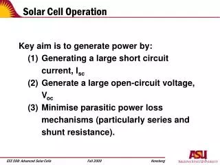
1 / 32
330 likes | 590 Vues
Introduction Into Solar Cell Study Using CIMPS. C. A. Schiller, ZAHNER-Messtechnik, -Thüringer Str. 12, D-96317 Kronach, Germany . Email: cas@zahner.de. Outline. Electrical and electrochemical solar energy conversion: problems and expectations.

E N D
Introduction Into Solar Cell Study Using CIMPS C. A. Schiller, ZAHNER-Messtechnik, -Thüringer Str. 12, D-96317 Kronach, Germany. Email: cas@zahner.de
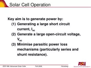
Outline • Electrical and electrochemical solar energy conversion: problems and expectations. • The analogy to fuel cells and batteries: solar cells and solar reactors as multiphase electrochemical systems. • The transfer function variables: light intensity, cell current and cell voltage. IMPS, IMVS and the analogy to EIS. • The instrumentation: light sources, calibration, potentiostats, and FRA. • Practical measurement considerations: limitations and artefacts. • Interpretation of CIMPS data: application example “Grätzel cell” and conducting polymer on TiO2. BASJ Seminar 2006 Nov - Introduction Into Solar Cell Study using CIMPS
Introduction (1) Global warming – CO2-production – renewable energy sources – environmental protection - they are the talk of the town. In this context, the utilization of solar energy will belong to the most public promoted activities for the next decades. Light induced processes like the photosynthesis in nature are of fundamental significance in the world. The favorite technical realization of the direct conversion from sunlight into clean electric energy is based on the “photoelectric effect”. It appears at illuminated interfaces like semiconductor junction barriers. All types of solar cells are based on the photo-electric effect. Besides this, electrochemical reactions, induced by the cheap solar light on photo-sensitive surfaces are hot candidates for the decontamination of harmful environmental poisons. BASJ Seminar 2006 Nov - Introduction Into Solar Cell Study using CIMPS
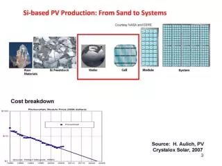
Introduction (2) Meanwhile crystalline silicon based solar cells reach impressing energy efficiency. But about ten Km2 ´s of worldwide installed SC area could damp neither the production costs nor the energy costs in ranges, competitive to traditional power plants. New cheap mass production SC technologies are in great demand. Some wishes are: • Production in printing techniques • flexible shape SC, which can be easily integrated in building walls • Renouncement on clean room procedures Dye Sensitized SC, Organic SC and amorphous SC based on alternative inorganic semiconductors are some of the research objects of high interest. BASJ Seminar 2006 Nov - Introduction Into Solar Cell Study using CIMPS
What to Do? Some of the problems which are unsolved: Poor efficiency, costs, degradation, toxicity, complexity. For alternative SC concepts often applies: the simpler they are, the less they are efficient. DSSC and alternative solar cells are very complex systems. The photo-active layer is embedded within several other phases. They support for instance the charge carrier separation, diffusion and collection. All components may contribute to the problems mentioned. It seems necessary to understand such a complex system. The origin of the problems may then be identified and goal-directed improvements are made possible. BASJ Seminar 2006 Nov - Introduction Into Solar Cell Study using CIMPS
Solar Cells and Solar Reactors As Multiple Compound Systems. Like fuel cells and batteries, solar cells and solar reactors are electrochemical systems consisting of several components. In a silicon solar cell, the room charge zone of the junction barrier, where the charge separation of the excitons takes place, is embedded in p-conducting and the n-conducting phases. These on the other hand are contacted with the metallic current collectors. The assembly of alternative solar cells is usually much more complex. BASJ Seminar 2006 Nov - Introduction Into Solar Cell Study using CIMPS
The “Grätzel” Cell A DSSC like the Grätzel cell contains a Dye, spread over a porous semiconductor. The dye supports the generation of the excitons. It is needed, because the band gap of the semiconductor, which assists the charge separation, usually has a too large band gap for an effective operation under sunlight. From the Dye, the electrons must go the long way to the transparent cathode contact through the semiconductor by diffusion, here the nano-porous n-type TiO2,. The holes have to be guided to the metallic anode contact by means of a p-conducting phase or an redox-mediator like the I--I3- -system. BASJ Seminar 2006 Nov - Introduction Into Solar Cell Study using CIMPS
The Three “Connection Lines” of a Solar Cell It is obvious, that solar cells can be evaluated by means of EIS using the electrical terminals as probes. But a general problem of EIS is, that from the pure impedance data two less “knowns” can be extracted for too much unknowns present. Fortunately, a solar cell has an additional “terminal”: the light intensity can be used as a third probe. Light intensity on the one hand and voltage or current on the other hand built two additional force-response couples, which can be used for a transfer function analysis besides EIS. BASJ Seminar 2006 Nov - Introduction Into Solar Cell Study using CIMPS
EIS, IMPS and IMVS Like EIS, IMPS and IMVS are methods, which measure dynamic transfer functions between an excitation force, applied to the system under test and the systems response function. In EIS, the couple of force and response is represented by the current through - and the voltage across an electrochemical cell. In a photo-sensitive system, the electric potential and the current flowing at the interface site are both depending on the illumination. Light intensity with photo-voltage on the one hand and light intensity with photo-current on the other hand are building the force-response couples. Compared to EIS, just one electrical signal is exchanged against the photo-intensity signal. BASJ Seminar 2006 Nov - Introduction Into Solar Cell Study using CIMPS
Comparison between EIS, IMPS and IMVS IMPS / IMVS Common: Small signal methods, expounding nonlinear time laws to linear approximations. Modulation of a steady state force and monitoring one response magnitude. The quotient of the dynamic magnitudes leads to the transfer function Z*. BASJ Seminar 2006 Nov - Introduction Into Solar Cell Study using CIMPS
A Reminder on the EIS Principle Modulation of the steady state force - current I (galvanostatic mode) or the voltage U (potentiostatic mode) at an electrochemical cell C. The quotient of the dynamic magnitudes leads to the Impedance Z* (or Admittance Y*=1/Z*). Other parameters, like the illumination intensity in case of a solar cell, has to be kept, until the transfer function record is completed. After that, the other parameters, like the intensity, may be swept. BASJ Seminar 2006 Nov - Introduction Into Solar Cell Study using CIMPS
IMPS and IMVS Principle Modulation of the light P as force, illuminating an electrochemical cell C. The quotient of one electric magnitude (current potentiostatic, or voltage galvanostatic or at OCP) with the dynamic light intensity P* leads to the IMPS / IMVS spectrum H*. The remaining magnitudes (for instance voltage or current) has to be kept, until the transfer function record is completed. After that, they may be swept. IMPS / IMVS BASJ Seminar 2006 Nov - Introduction Into Solar Cell Study using CIMPS
The Catch of IMPS Known in Literature = : Steady state set value U: Cell voltage I: Cell current C: Cell LED: Light emitting diode FRA: Frequency response analyzer The literature IMPS set-up: The function generator output of an FRA supplies an LED light source with modulated current. The cell current (or voltage) is correlated with the LED current to calculate the photo-electrochemical transfer function H*. Problem: No control over the long term and momentary intensity. BASJ Seminar 2006 Nov - Introduction Into Solar Cell Study using CIMPS
The Drawbacks • Unstable intensity time drift, degradation, missing reproducibility • Nonlinear Modulation harmonic distortion interference • Unknown Modulation depth scale factor error, un-calibrated results • Phase shift control current vs. intensity Transfer function phase error • Traditional IMPS cannot produce accurate relationships between EIS-, IMPS-, IMVS-data and illumination intensity. • Traditional IMPS cannot produce comparable EIS-, IMPS- and IMVS-results measured at the same state of the systems under test. BASJ Seminar 2006 Nov - Introduction Into Solar Cell Study using CIMPS
The Solution: Controlled Intensity Modulated Photo Spectroscopy CIMPS The point is: an Operational Amplifier, working as a “potentiostat”, can supply the LED light source with electric energy. A voltage can be measured when the actual intensity is monitored at the site of the cell by means of a photo-sense-amplifier (based on a fast photo-diode). This voltage is an exact measure of the intensity. The voltage can be used as feedback signal to the potentiostat. The potentiostat will regulate the energy in a way, that the measured voltage will exactly follow a set-voltage. A certain set-voltage can now generate an exactly calibrated intensity at the site of the cell in well defined proportionality. A certain modulation of the set-voltage will cause an accurately determined light intensity modulation. The introduction of the measured intensity in the FRA as force signal will avoid all absolute scaling and phase errors. BASJ Seminar 2006 Nov - Introduction Into Solar Cell Study using CIMPS
Comparison between IMPS and CIMPS FRA: Frequency Response Analyzer IM6-FRA: Electrochemical Workstation IM6/IM6ex *) EPOT: Slave-Potentiostat - Power OPA XPOT or PP210 *) PD/PSA: UV-VIS-NIR Photo detector / Sense Amplifier *) BUVZ/GRL: UV-VIS Multi-LED-Emitter (many different other wavelength emitters available) *) *) : Content of the ZAHNER CIMPS Equipment Common: LEDs as fast and easy controllable light sources. Different: The measured intensity is used as force signal information. The actual intensity is controlled with a photo-sensor at the site of the cell and regulated by means of an operational amplifier feedback circuit. BASJ Seminar 2006 Nov - Introduction Into Solar Cell Study using CIMPS
The Electrical Hardware: Two Different Basic Configurations The CIMPS system comes up in different device configurations: XPOT as slave High sensitivity-medium power. PP210 as slave Medium sensitivity-high power. BASJ Seminar 2006 Nov - Introduction Into Solar Cell Study using CIMPS
The Optical Hardware Top: The photo-electrochemical cell „PECC“ and the photo-sensor. Left: front view, right: top view. Bottom: The carrier unit for LED emitters. It includes the photo-sense-amplifier. Optical bench and PECC shown in side view. BASJ Seminar 2006 Nov - Introduction Into Solar Cell Study using CIMPS
The Calibration Set Up For an exact on-site intensity calibration, CIMPS can be delivered together with a NIST traceable photo-sensor. For calibration, it has to be mounted instead of the PECC at the same position. The calibration is supported as push-button procedure. BASJ Seminar 2006 Nov - Introduction Into Solar Cell Study using CIMPS
Limitations and Artefacts • Due to the nature of the photo-electric effect, the electric response on the intensity may be small. Besides this, inherent inertia will entail, that the efficiency is getting smaller or even vanishes for higher frequencies. • The electrical signals necessary for the light modulation in turn, cause electromagnetic interference, increasing with the frequency. • A characteristic high frequency limit for all IMPS/IMVS techniques is the consequence. • The larger the photo-electric effect is, the higher is the upper frequency limit. • An additional frequency limit is given by the hardware bandwidth of fg 250 KHz (XPOT version) and fg 100 KHz (PP210 version). BASJ Seminar 2006 Nov - Introduction Into Solar Cell Study using CIMPS
Controlled Intensity Modulated Photo- and Impedance Spectroscopy on Dye Sensitized Solar Cell Components W. Plieth1, C.A. Schiller2, U. Rammelt1, U. Würfel3 1Dresden University of Technology, Institute of Physical Chemistry and Electrochemistry, Mommsenstr. 13, D-010602 Dresden, Germany 2ZAHNER-Messtechnik, Thüringer Str. 12, D-96317 Kronach, Germany 3 Freiburg Materials Research Center (FMF), Stefan-Meier-Straße 21, D-79104 Freiburg i. Br., Germany BASJ Seminar 2006 Nov - Introduction Into Solar Cell Study using CIMPS
Experimental In the present work, nano-porous TiO2 on SnO2 -TCO glass substrate in an electrolyte containing an Iodine redox couple was examined. The TiO2 was sensitized with the Ruthenium Dye complex N719. The schematic depicts the layers at the photo-sensitive side. The Pt-counter electrode and the Ag/AgCl reference electrode, present in the practical set-up, is omitted. BASJ Seminar 2006 Nov - Introduction Into Solar Cell Study using CIMPS
The PECC Set-Up The Grätzel type cell was studied in an half cell arrangement. For that, the Zahner standard PECC had to be modified. The usual light entry through the window at the counter electrode side had to be changed against a light entry from the rear side (TCO on glass) of the TiO2-glass carrier. Electrolyte: Acetonitrile + I3- / I- Light beam = 530 nm PECC cross section BASJ Seminar 2006 Nov - Introduction Into Solar Cell Study using CIMPS
The Experimental Hardware Devices A typical CIMPS set-up supported by Zahner was used. It consists of an electrochemical workstation IM6ex, an XPOT slave potentiostat, an optical bench with the carrier for the light source, including the sense amplifier, the photodiode-sensor and the modified PECC with the built in Ag/AgCl reference electrode and a Pt counter electrode. BASJ Seminar 2006 Nov - Introduction Into Solar Cell Study using CIMPS
Measurements and Results Concerning the complexity of the system under test, a systematic measurement plan seemed to be favourable. By means of (here not presented) static measurements of the photocurrent efficiency at wavelengths between 650 and 365 nm, a flat efficiency maximum was found for green light. A quantum efficiency between 15 to 20 % was observed. The following dynamic measurements were then performed under 530 nm green light in an intensity range between 1 and 55 W/m2. BASJ Seminar 2006 Nov - Introduction Into Solar Cell Study using CIMPS
EIS Measurements at OCP Here is the result of the impedance measurements at open circuit potential (OCP) under different illumination intensities. At OCP one finds a decreasing low frequency impedance due to an increased forward biasing of the photo-junction.This experiment is sensitive to the photo-junction impedance changes. The recombination of photo-generated charge is the major dissipation mechanism. The electrochemical double layer does not change significantly. BASJ Seminar 2006 Nov - Introduction Into Solar Cell Study using CIMPS
EIS Measurements at Fixed Potential Here the impedance measurements at fixed potential (darkness OCP) as a function of different illumination densities is plotted. The dominant changes in the observed spectra is due to the polarization of the electrochemical double layer, accompanied by only a small forward biasing of the photo-junction as side effect. This type of experiment is sensitive to the changes of the double layer impedance and therefore offers an access to the properties of the electrochemical processes. BASJ Seminar 2006 Nov - Introduction Into Solar Cell Study using CIMPS
Dynamic Photo-Current (CIMPS) Here the dynamic photo-current measurements (IMPS) at fixed potential (darkness OCP) under different illumination intensities are depicted. At constant voltage and at closed outer circuit, the dynamic behavior of the outer photocurrent is mainly determined by the photocurrent generating process,but affected by the complete impedance network. BASJ Seminar 2006 Nov - Introduction Into Solar Cell Study using CIMPS
Dynamic Photo-Voltage (CIMVS) Here the dynamic photo-voltage measurements (IMVS) at fixed current (values were registrated, while the IMPC was measured) are depicted. At constant current, the dynamic behavior of the photo voltage is mainly determined by the photocurrent generating process and the impedance of the photoactive layer. The effective network is simplified, because the influence of the series impedance is cancelled out. BASJ Seminar 2006 Nov - Introduction Into Solar Cell Study using CIMPS
Discussion (1) Each of the presented electrochemical techniques emphasizes certain parts of a common model. By this, the assignment of the model components facilitated, provided that the stability of the system during the experiments is ensured. Especially, the illumination conditions have to be controlled properly. This is the task of the CIMPS technique presented here. As a result, a common model for the photo-voltage- as well as the corresponding photo-current spectra of the series was found. 1: Photo current source 2: Forward resistance 3: Diffusion impedance 4: Chemical capacity 5: Charge transfer resistance 6: Double layer capacity 7: Electrolyte resistance BASJ Seminar 2006 Nov - Introduction Into Solar Cell Study using CIMPS
Discussion (2) The Nyquist representation of the photo-voltage- (red) as well as the corresponding photo-current (blue) spectrum of the series was simulated by the equivalent circuit depicted on the slide before. The comparison between the simulated (line) and the measured (circles) data is excellent. BASJ Seminar 2006 Nov - Introduction Into Solar Cell Study using CIMPS
Dummy Circuit Control Experiment Testing the models and the evaluation strategy by means of CIMPS voltage and current measurements on a dummy circuit network containing a photo diode under illumination. BASJ Seminar 2006 Nov - Introduction Into Solar Cell Study using CIMPS