Download
1 / 90
960 likes | 1.94k Vues
Chapter 1. Three-Phase System. 1.1: Review of Single-Phase System The Sinusoidal voltage v 1 (t) = V m sin w t. i. v 1. v 2. Load. AC generator. 1.1: Review of Single-Phase System The Sinusoidal voltage v (t) = V m sin w t where V m = the amplitude of the sinusoid

E N D
Chapter 1. Three-Phase System
1.1: Review of Single-Phase System The Sinusoidal voltage v1(t) = Vm sin wt i v1 v2 Load AC generator
1.1: Review of Single-Phase System The Sinusoidal voltage v(t) = Vm sin wt where Vm = the amplitude of the sinusoid w = the angular frequency in radian/s t = time
A more general expression for the sinusoid (as shown in the figure): v2(t) = Vm sin (wt + q) where q is the phase
A sinusoid can be expressed in either sine or cosine form. When comparing two sinusoids, it is expedient to express both as either sine or cosine with positive amplitudes. We can transform a sinusoid from sine to cosine form or vice versa using this relationship: sin (ωt ± 180o) = - sin ωt cos (ωt ± 180o) = - cos ωt sin (ωt ± 90o) = ± cos ωt cos (ωt ± 90o) = + sin ωt
Sinusoids are easily expressed in terms of phasors. A phasor is a complex number that represents the amplitude and phase of a sinusoid. v(t) = Vm cos (ωt + θ) Time domain Phasor domain
Time domain v2(t) = Vm sin (wt + q) v1(t) = Vm sinwt Phasor domain V2 or θ or V1
1.1.1: Instantaneous and Average Power The instantaneous power is the power at any instant of time. p(t) = v(t) i(t) Where v(t) = Vm cos (wt + qv) i(t) = Im cos (wt + qi) Using the trigonometric identity, gives
The average power is the average of the instantaneous power over one period.
The effective value is the root mean square (rms) of the periodic signal. The average power in terms of the rms values is Where
1.1.2: Apparent Power, Reactive Power and Power Factor The apparent power is the product of the rms values of voltage and current. The reactive power is a measure of the energy exchange between the source and the load reactive part.
The power factor is the cosine of the phase difference between voltage and current. The complex power:
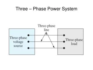
1.2: Three-Phase System In a three phase system the source consists of three sinusoidal voltages. For a balanced source, the three sources have equal magnitudes and are phase displaced from one another by 120 electrical degrees. A three-phase system is superior economically and advantage, and for an operating of view, to a single-phase system. In a balanced three phase system the power delivered to the load is constant at all times, whereas in a single-phase system the power pulsates with time.
1.3: Generation of Three-Phase Three separate windings or coils with terminals R-R’, Y-Y’ and B-B’ are physically placed 120o apart around the stator.
V or v is generally represented a voltage, but to differentiate the emf voltage of generator from voltage drop in a circuit, it is convenient to use e or E for induced (emf) voltage.
The instantaneous e.m.f. generated in phase R, Y and B: eR= EmRsin wt eY= EmY sin (wt -120o) eB= EmB sin (wt -240o)= EmBsin (wt +120o) 17
Three-phase AC generator IR VR ZR ER IN EB VB VY EY ZB ZY IY IB Three-phase Load
Phase voltage The instantaneous e.m.f. generated in phase R, Y and B: eR= EmRsin ωt eY= EmY sin (ωt -120o) eB= EmB sin (ωt -240o)= EmBsin (ωt +120o) In phasor domain: 120o ER = ERrms 0o 0o EY = EYrms -120o -120o EB = EBrms 120o Magnitude of phase voltage ERrms = EYrms = EBrms = Ep
Three-phase AC generator Line voltage IR ERY VR ZR ER IN EB VB VY EY ZB ZY IY IB ERY = ER - EY Three-phase Load
Line voltage ERY = Ep 0o - Ep -120o ERY -EY = 1.732Ep 30o = √3 Ep 30o 120o 0o 30o = EL -120o ERY = ER - EY
Three-phase AC generator Line voltage IR VR ZR ER IN EB VB VY EY ZB ZY IY IB EYB EYB = EY - EB Three-phase Load
Line voltage 120o EYB = Ep -120o - Ep 120o = 1.732Ep -90o 0o = √3 Ep -90o -90o -120o = EL -EB EYB EYB = EY - EB
Three-phase AC generator Line voltage IR VR ZR ER EBR IN EB VB VY EY ZB ZY IY IB EBR = EB - ER Three-phase Load
Line voltage EBR = Ep 120o - Ep 0o EBR 120o = 1.732Ep 150o 0o = √3 Ep 150o 150o -ER -120o = EL For star connected supply, EL= √3 Ep EBR = EB - ER 25
Phase voltages It can be seen that the phase voltage ER is reference. ER = Ep 0o EY = Ep -120o EB = Ep 120o 120o 0o Line voltages -120o ERY = EL 30o EYB = EL -90o EBR = EL 150o
Phase voltages Or we can take the line voltage ERY as reference. ER = Ep -30o EY = Ep -150o EB = Ep 90o Line voltages ERY = EL 0o EYB = EL -120o EBR = EL 120o 27
Three-phase AC generator Delta connected Three-Phase supply IR ERY VR ZR ER EB VB VY EY ZB ZY IY IB Three-phase Load ERY = ER = Ep 0o
Three-phase AC generator Delta connected Three-Phase supply IR VR ZR ER EB VB EBR VY EY ZB ZY IY IB EYB Three-phase Load For delta connected supply, EL= Ep
Connection in Three Phase System 4-wire system (neutral line with impedance) 3-wire system (no neutral line ) 4-wire system (neutral line without impedance) 3-wire system (no neutral line ), delta connected load Star-Connected Balanced Loadsa)4-wire system b) 3-wire system Delta-Connected Balanced Loadsa) 3-wire system
4-wire system (neutral line with impedance) Three-phase AC generator IR VR ZR ER ZN IN EB VB VN VY EY ZB ZY IY IB 1.1 Three-phase Load Voltage drop across neutral impedance: VN = INZN
4-wire system (neutral line with impedance) Three-phase AC generator Applying KCL at star point IR VR ZR ER ZN IN EB VB VN VY EY ZB ZY IY IB 1.2 Three-phase Load IR + IY + IB= IN
4-wire system (neutral line with impedance) Three-phase AC generator Applying KVL on R-phase loop IR VR ZR ER ZN IN EB VB VN VY EY ZB ZY IY IB Three-phase Load
4-wire system (neutral line with impedance) Three-phase AC generator Applying KVL on R-phase loop IR VR ZR ER ZN IN VN ER – VR – VN = 0 ER – IRZR – VN = 0 Thus ER – VN IR = 1.3 Three-phase Load ZR
4-wire system (neutral line with impedance) Three-phase AC generator Applying KVL on Y-phase loop IR VR ZR ER ZN IN EB VB VN VY EY ZB ZY IY IB Three-phase Load
4-wire system (neutral line with impedance) Three-phase AC generator Applying KVL on Y-phase loop EY – VY – VN = 0 Thus EY – VN IY = EY – IYZY – VN = 0 ZY ZN IN VN VY EY ZY IY 1.4 Three-phase Load
4-wire system (neutral line with impedance) Three-phase AC generator Applying KVL on B-phase loop EB – VB – VN = 0 Thus EB – VN IB = EB – IBZB – VN = 0 ZB ZN IN EB VB VN ZB IB 1.5 Three-phase Load
4-wire system (neutral line with impedance) Substitute Eq. 1.2, Eq.1.3, Eq. 1.4 and Eq. 1.5 into Eq. 1.1: IR + IY + IB= IN ER – VN EY – VN EB – VN VN = + + ZR ZY ZB ZN 1 EB 1 1 1 VN EY ER ER – VN EY – VN EB – VN + = + ZR ZR ZY ZY ZB ZB ZN ZY ZB ZB ZN ZY ZR ZR VN + + = + + +
4-wire system (neutral line with impedance) + + VN = 1 1 1 ER EY EB 1 + + + ZY ZB ZY ZR ZN ZR ZB ER EY EB 1 1 1 1 VN + + = + + + 1.6 ZR ZY ZB ZN ZR ZY ZB
4-wire system (neutral line with impedance) VN is the voltage drop across neutral line impedance or the potential different between load star point and supply star point of three-phase system. + + VN = ER 1 1 1 1 EY EB + + + ZB ZY ZN ZB ZY ZR ZR We have to determine the value of VN in order to find the values of currents and voltages of star connected loads of three-phase system. 1.6
Example IR EL = 415 volt VR ZR = 5 Ω ER ZN =10 Ω IN EB VB VN ZY= 2 Ω EY ZB = 10 Ω IY IB Find the line currents IR ,IY and IB. Also find the neutral current IN. Three-phase Load
3-wire system (no neutral line ) Three-phase AC generator IR VR ZR ER ZN IN EB VB VN VY EY ZB ZY IY IB Three-phase Load
3-wire system (no neutral line ) Three-phase AC generator IR VR ZR ER VN EB VB VY EY ZB ZY IY IB Three-phase Load No neutral line = open circuit , ZN = ∞
3-wire system (no neutral line ) + + VN = 1 + + + ZN EY 1 1 1 1 EB ER ∞ ZR ZB ZB ZR ZY ZY ZN = ∞ ∞ = 0 1.6
3-wire system (no neutral line ) + + VN = + + 1 1 1 EB EY ER ZY ZR ZY ZB ZR ZB 1.7
Example IR EL = 415 volt VR ZR = 5 Ω ER EB VB VN ZY= 2 Ω EY ZB = 10 Ω IY IB Find the line currents IR ,IY and IB . Also find the voltages VR, VY and VB. Three-phase Load
3-wire system (no neutral line ),delta connected load Three-phase AC generator IR VR ZR ER EB VB VY EY ZB ZY IY IB Three-phase Load
3-wire system (no neutral line ),delta connected load Three-phase AC generator IR Ir ER VRY VBR ZRY ZBR EB Ib ZYB EY Iy IY VYB IB Three-phase Load
3-wire system (no neutral line ),delta connected load Three-phase AC generator IR Ir ERY =VRY ER VRY VBR ZRY EBR ZBR =VBR EB EY Ib ZYB Iy IY VYB IB EYB =VYB Three-phase Load
3-wire system (no neutral line ),delta connected load Phase currents 30o Ir = = = -90o Iy = = = VRY ERY EBR EL EL EL EYB VBR VYB 150o ZYB ZBR ZBR ZYB ZRY ZRY ZRY ZYB ZBR Ib = = =