Download
1 / 12
130 likes | 266 Vues
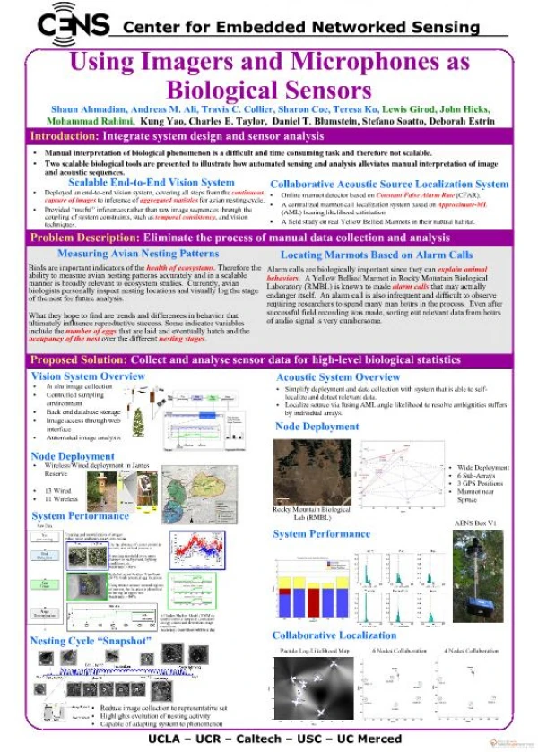
Spherically Curved CCD Imagers for Passive Sensors. J. A. Gregory, A. M. Smith, E. C. Pearce, R. L. Lambour, R. Y. Shah, H. R. Clark, K. Warner, R. M. Osgood III, D. F. Woods, A. E. DeCew, S. E. Forman, L. Mendenhall, C. M. DeFranzo , V. S. Dolat, and A. H. Loomis .

E N D
Spherically Curved CCD Imagers for Passive Sensors J. A. Gregory, A. M. Smith, E. C. Pearce, R. L. Lambour, R. Y. Shah, H. R. Clark, K. Warner, R. M. Osgood III, D. F. Woods, A. E. DeCew, S. E. Forman, L. Mendenhall, C. M. DeFranzo, V. S. Dolat, and A. H. Loomis *This work was sponsored the Defense Advanced Research Projects Agency (DARPA)/Tactical Technology Office (TTO) under Air Force contract number FA8721-05-C-0002. Opinions, interpretations, conclusions, and recommendations are those of the authors and are not necessarily endorsed by the United States Government.
Deforming Si and its effects on CCDs Curved sensor examples Charge-coupled device (CCD) petal chip Space Surveillance Telescope Outline
Si sheets of 50-µm thickness can withstand large deformation Single crystal material has failure strain, eF, ≈ 1.2% (sF ≈ 2 GPa) Corresponds to ≈0.2 steradian (sr) coverage of a convex or concave sphere Allows for ≈30° field of view, with only weak thickness dependence Tensile load needed to avoid buckling while deforming spherically Buckling tendency increases with solid angle covered Deforming Thin Si Sheets Spherical Deformation with Buckling Over a Glass Lens Large-Strain (≈1%) Cylindrical Deformation
Spherically Deforming Thinned Devices • Out-of-plane displacement • Good agreement for thickness and pressure dependence with analytical model • Qualitative agreement for orientation dependence • Induced tangential tensile stress eliminates buckling Clamp Ring Top View 40 mm Side View of Thinned CCD Pressure Chamber View Pressure chamber for stressing CCD CCD with Central Thinned Section
Effect of Strain on Dark Current • Dark current reaches maximum at center of deformed CCD (maximum strain) T = -50˚C 575 kPa Calculated strain vs. position Change of scaled ID with position across thinned section
Scaled Dark Current (ID) vs. Pressure • Effects can be modeled as strain-dependent reduction in bandgap • ID= CT2exp[-(Eg0 + ∂Eg/∂e•|De|)/2kT] • ∂Eg/∂e (-80 meV/%) agrees well with handbook values • No permanent degradation below eF
Petal-Chip CCDs for Wider FOV Overlapping of petals during deformation allows for greater solid-angle coverage • Cover 1.14 sr • 70° object field-of-view • Focal-sphere radius of 15 mm • 16 petals surround central disk • Pixel dimensions ~ 24 mm, radially and tangentially • Image array only, no frame store • Polar array of pixels • Rings and columns • 390,000 pixels • 360 rings out to serial register • Successive rings contain increasing numbers of pixels • Column length variable • Serial register • Along circumference of each petal Examples of petal chips covering 1.4 sr 54-mm-diameter petal membrane extracted from thinned Si wafer Petal membrane deformed about 38-mm-radius spherical mandrel
Fully Populated Space Surveillance Telescope Focal Surface 12 CCDs mounted to 5.44-m radius of curvature within 3 µm CCD: 2 k × 4 k, 15-µm pixels Space Surveillance Telescope, 3.5 m, f/1
Vacuum-Assisted Bonding to Curved Mandrels • Vacuum chuck • Machined to desired curvature • Eliminates buckling; places membrane in tension 150 mm
Radius of curvature confirmed:5.446 m vs. 5.440-m target 3µm RMS surface deviation Profile Scan Results: CCD Held by Vacuum Chuck
Post-Bonding Measurements Surface scan data • Conformance to 5.44-m radius is < 1.7 µm rms for CCD • Within 3 µm for all CCDs in focal-plane array • Maximum strain < 3×10⁻⁵ (<< failure strain) • Dark current, CTE and cosmetics unchanged Units = mm for all scales
Deforming Si and its effects on CCDs Principal effect is increased dark current No observed effect on CTE Curved sensor examples Charge-coupled device (CCD) petal chip 70˚ FOV Mechanical model demonstrated; CCD fabricated but not thinned Space Surveillance Telescope First use of curved CCDs in large focal-surface array Operational for ~1.5 years Summary