Download
1 / 20
200 likes | 376 Vues
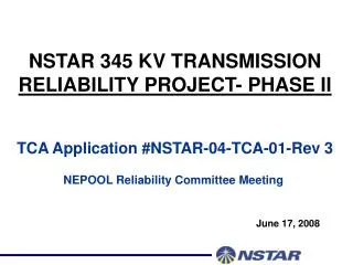
NSTAR 345 kV Reliability Project Switching Transient Analysis. 12/13/2004 Presentation To Reliability Committee. What Was Studied. Frequency Scan / Harmonic Resonance Analysis Energization Cases Cables & Transformers Synchronous closing versus pre-insertion resistor breakers

E N D
NSTAR 345 kV Reliability Project Switching Transient Analysis 12/13/2004 Presentation To Reliability Committee
What Was Studied • Frequency Scan / Harmonic Resonance Analysis • Energization Cases • Cables & Transformers • Synchronous closing versus pre-insertion resistor breakers • Fault Clearing Cases • 1 ph-gnd & 3 ph faults • Reclosing OH lines • 15 fault locations
EMTP Model Transmission System Study Area
345 kV Project Model System Model For: Fault Clearing Cases Cable Energizing Cases
EMTP Model • Shunt Capacitors and Reactors
EMTP Model • Generation
EMTP Model • Load • Peak load for study area = 3500MW
Harmonic Resonance Screening • Analysis used to identify locations to monitor • Harmonic resonance below 3rd can aggravate transient problems but is not a problem itself • Value and intent is to target locations where overvoltage conditions may be introduced
Study Results • Energizing cases simulated for: • 345 kV cables from Stoughton to K Street and Hyde Park • 345/115 kV Transformers at K Street, Hyde Park & Holbrook • Above cases with Stoughton - Walpole / Stoughton - Holbrook out of service • Above cases for closing into a fault • Results indicate need for point on wave switching (i.e. synchronous closing) or pre-insertion resistors for breakers at Stoughton • Fault clearing cases for faults at K Street, Hyde Park, Stoughton, Walpole & Holbrook • Results indicate that line out of service conditions at Stoughton are a concern
Breaker Type Pre-Insertion Resistor Synchronous Closing Voltage Min. Closing1 345 kV Line 300-600 345 kV Cable 80-100 Voltage Min. Closing 80-600 345 kV / 115 kV Auto No optimum closing voltage available No optimum closing voltage available 345 kV Shunt Reactor 80-600 Optional Surge arresters recommended - Provides back-up for timing failure or large timing error Line/Cable Surge Arresters Study Results • Circuit breaker performance by equipment: 1Energizing only. Investigate reclosing capabilities with vendor.
Pre-Insertion Resistor Synchronous Closing √ 345 kV Line √ 345 kV Cable and 0 MVAR √ √ 345 kV Cable and 70 MVAr √ √ 345 kV cable with 100 MVAr √ √ NR √ 345 kV cable with 160 MVAr √, NO 345 kV/ 115 kV Auto- transformer or 345 kV Shunt Reactor √ Study Results • Circuit breaker performance according to system operation: Key: √- Permitted, NR – Not recommended, NO – Not optimized
Study Results • Circuit breaker transient recovery voltages (TRV) • Single and three phase faults simulated • Single phase TRVs: • Higher than 3 phase TRVs: 755 kV, 723 kV, …….. • Single phase capability: 827 kV (IEC) • Three phase TRVs: • Three phase TRVs: 552 kV, 519 kV, 517 kV, … • Out-of-phase switching capability: 739 kV (IEC)
Breaker Selection • Based on results for equipment energization the following breaker types will be employed: • Stoughton 345 kV Ring Bus – Pre-Insertion Resistor • Stoughton 345 kV Reactors – Synchronous Closing • K Street 345 kV Bus / Reactors – Synchronous Closing • Hyde Park 345 kV Bus – Synchronous Closing • The 345 kV cables will only be energized from the Stoughton 345 kV bus
Study Results • Surge Arresters • NSTAR standard unit: 276 kV rating, 224 kV MCOV • This unit consistent with: • Expected steady state system operation voltage • All Fault clearing TOVs, except two cases: • Single phase fault on 316, 3161 out of service • Three phase fault on 316, 3161 out of service • Similar results expected for faults on 3161 with 316 out of service • SPS needed to avoid multi-column units for Stoughton – Walpole / Stoughton – Holbrook line out of service conditions
SPS Design Transfer Trip These Breakers Transfer Trip These Breakers Transfer Trip These Breakers Out of Service Communications will be fully redundant additional protection will be provided through surge arrestors Faulted Line
SPS Design • SPS will be armed whenever either the Stoughton to Walpole or the Stoughton to Holbrook 345 kV lines are out of service • Reclosing for the 345 kV line that remains in service will be disabled when the SPS is armed • 345 kV Reactors will be set to a total compensation level of at least 400 MVAR any time the Stoughton – Walpole line is out. (Insures acceptable response for faults at Holbrook)
BIL Chopped Wave Full Wave Switching Surge 1175 77 % 82% 76% 1050 58% 63% 57% Study Results Equipment Insulation: Equipment Protection:
Conclusions • Based on transient analysis studies the NSTAR 345 kV Project will more than meet all transient overvoltage requirements of specified equipment provided: • Transfer trip scheme (SPS) is employed for 345 kV overhead line out of service conditions • Reactors will be set to minimum compensation levels for line out of service conditions • Surge arrestors are deployed per study specifications • Appropriate selection of breaker specifications (synchronous closing or pre-insertion resistor type) for equipment energization (i.e. cables, reactors, lines & transformers) • NSTAR will implement all of the above design requirements as part of the initial installation of the project