Download
1 / 24
270 likes | 474 Vues
JPEG Compression. Indiana University Purdue University Fort Wayne Hongli Luo. The JPEG Standard. JPEG is an image compression standard that was developed by the “Joint Photographic Experts Group”. JPEG was formally accepted as an international standard in 1992.

E N D
JPEG Compression Indiana University Purdue University Fort Wayne Hongli Luo
The JPEG Standard • JPEG is an image compression standard that was developed by the “Joint Photographic Experts Group”. JPEG was formally accepted as an international standard in 1992. • JPEG is a lossy image compression method. It employs a transform coding method using the DCT (Discrete Cosine Transform). • An image is a function of i and j (or conventionally x and y) in the spatial domain. • The 2D DCT is used as one step in JPEG in order to yield a frequency response which is a function F(u, v) in the spatial frequency domain, indexed by two integers u and v.
Observations for JPEG Image Compression • The effectiveness of the DCT transform coding method in JPEG relies on 3 major observations: • Observation 1: Useful image contents change relatively slowly across the image, i.e., it is unusual for intensity values to vary widely several times in a small area, for example, within an 8 x 8 image block. • much of the information in an image is repeated, hence “spatial redundancy”.
Observations for JPEG Image Compression(cont'd) • Observation 2: Psychophysical experiments suggest that humans are much less likely to notice the loss of very high spatial frequency components than the loss of lower frequency components. • the spatial redundancy can be reduced by largely reducing the high spatial frequency contents. • JPEG uses DCT to reduce high-frequency contents and then efficiently code the results into a string • Observation 3: Visual acuity (accuracy in distinguishing closely spaced lines) is much greater for gray (“black and white”) than for color. • chroma subsampling (4:2:0) is used in JPEG.
Main Steps in JPEG Image Compression • JPEG works for both color and grayscale image • For color image, such as YIQ or YUV, the encoder works on each component separately, using the same routine. • If the source image is in a different color format, the encoder performs a color-space conversion to YIQ or YUV. • The chrominance images (I,Q, or U,V) are subsampled using 4:2:0.
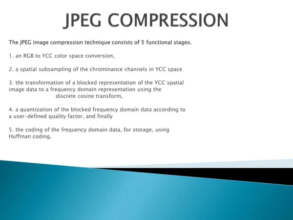
Main Steps in JPEG Image Compression • Main Steps in JPEG Image Compression • Color space transform - transform RGB to YIQ or YUV • Each channel is coded independently • Subsample color. • Perform DCT on image blocks. • Quantization • Coefficients are quantized • Reduce the total number of bits needed for a compressed image • Zig-zag scan • DPCM on DC coefficients • Run-length encoding on AC coefficients • Entropy coding on DCT coefficients (Huffman or Arithmetic)
Main Steps in JPEG Image Compression • When the JPEG image is needed for viewing, the three compressed images can be decoded independently and eventually combined. • For the color channels, each pixel must be first enlarged to cover a 2 x 2 block.
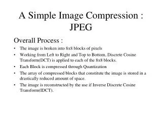
DCT on image blocks • Each image is divided into 8 x8 blocks. The blocks are processed from left to right and from top to bottom. • 8x8 makes the DCT/IDCT computation very fast • The 2D DCT is applied to each block image f(i, j), with output being the DCT coefficients F(u, v) for each block. • Using blocks, however, has the effect of isolating each block from its neighboring context. This is why JPEG images look choppy (“blocky”) when a high compression ratio is specified by the user. • The DCT coefficient represents the spatial frequency components within a 8x8 image block. • The (0, 0) coefficient is DC coefficient, which is equal to the average value of the 64 pixel values in the block.
DCT Coefficient Quantization • F(u, v) represents a DCT coefficient, Q(u, v) is a “quantization matrix” entry, and represents the quantized DCT coefficients which JPEG will use in the succeeding entropy coding. • The quantization step is the main source for loss in JPEG compression. • The entries of Q(u, v) tend to have larger values towards the lower right corner. This aims to introduce more loss at the higher spatial frequencies - a practice supported by Observations 1 and 2. • Table 9.1 and 9.2 show the default Q(u, v) values obtained from psychophysical studies with the goal of maximizing the compression ratio while minimizing perceptual losses in JPEG images.
DCT Coefficient Quantization • Purpose of quantization • reduce the total number of bits needed for a compressed image. • Low-frequency coefficients usually have more energy than high-frequency coefficients • Low-frequency coefficients require small quantization values. • The human visual system is more sensitive to low frequencies • Low-frequency coefficients require small quantization values. • The human visual system is more sensitive to luminance to chrominance • Luminance channels requires smaller quantization values than chrominance channels
DCT Coefficient Quantization • To change the compression ratio • Simply by multiplicatively scaling the numbers in the Q(u,v) matrix. • Quality factor • A user choice offered in every JPEG implementation • Linearly tied to the scaling factor • JPEG also allows custom quantization tables to be specified and put in the header.
DCT Coefficient Quantization • f(i,j) – block image • F(u,v) - DCT coefficients for each block • Q(u,v) - Quantization matrix entry • - quantized DCT coefficients • - de-quantized DCT coefficients • - reconstructed image block • e(i,j) - error
DCT Coefficient Quantization • Figure 9.2, an image block is chosen at the area where the luminance values change smoothly. • Contains few high-spatial-frequency changes • Most of the DCT coefficients have small magnitudes • Figure 9.3, the image block chosen has rapidly changing luminance • Many more AC components have large magnitudes • The error e is larger than in Figure 9.2 • JPEG introduce more loss if the image has quickly changing details.
Zig-zag Scan • Zig-zag Scan turns the 8 x 8 matrix into a 64-vector. • Most image blocks tend to have small high-spatial-frequency components, which are zeroed out by quantization. • Zig-zag scan order concatenates long runs of zeros.
Preparation for Entropy Coding – run-length coding on ACs • The zigzag scan order has a good chance of concatenating long runs of zeros. • For example, in Figure 9.2 will be turned into (32, 6, -1, -1, 0, -1, 0,0,0,-1, 0,0, 1, 0,0, …, 0) • Replace values by a pair (RUNGLENGTH, VALUE) for each run of zeros in the AC coefficients. • RUNLENGTH is the number of zeros in the run • VALUE is the next nonzero coefficient. • A special pair (0,0) indicates the end-of-block. • Not considering the first (DC) component, we will have (0,6)(0,-1) (0,-1)(1,-1)(3,-1)(2,1)(0,0)
Preparation for Entropy Coding – DPCM on DCs • DC reflects the average intensity values of each block. There is usually strong correlation between the DC coefficients of adjacent blocks. • The DC coefficients are coded separately from the AC ones. Differential Pulse Code Modulation (DPCM) is the coding method. • If the DC coefficients for the first 5 image blocks are 150, 155, 149, 152, 144, then the DPCM would produce 150, 5, -6, 3, -8, assuming di = DCi+1− DCi, and d0=DC0. • DPCM for the DC coefficients in JPEG is carried out on the entire image.
Entropy Coding • The DC and AC coefficients finally undergo an entropy coding step to gain a possible further compression. • Use DC as an example: each DPCM coded DC coefficient is represented by (SIZE, AMPLITUDE), • SIZE indicates how many bits are needed for representing the coefficient, • AMPLITUDE contains the actual bits. • In the example we're using, codes 150, 5, −6, 3, −8 will be turned into (8, 10010110), (3, 101), (3, 001), (2, 11), (4, 0111) . • SIZE is Huffman coded since smaller SIZEs occur much more often. • AMPLITUDE is not Huffman coded, its value can change widely so Huffman coding has no appreciable benefit.