Download
1 / 15
150 likes | 154 Vues
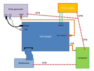
Test of moving the HV Board. Marco, John, Bill G., Bill T.,Howard. Test Setup. HV board moved to a box HV input and cable output. TDR test. Typical TDR picture Need to digitize distorted picture Use computer software to pick out points 50 Ω 29.5 pF/ft 0.070 µ H/ft

E N D
Test of moving the HV Board Marco, John, Bill G., Bill T.,Howard HM
Test Setup • HV board moved to a box • HV input and cable output HM
TDR test • Typical TDR picture • Need to digitize distorted picture • Use computer software to pick out points • 50 Ω • 29.5 pF/ft • 0.070 µH/ft • nominal delay 1.46 ns/ft. HM
TDR Photos HM
Raw versus Extension Raw Chamber Q1 Can see structures in the circuit board HM
Fit Curve to an Exponential • Good fit to an exponential • RC = 5.0357 ns HM
Move to ALS • Detector in the beam line • Cables outside • Chamber just worked • Used it to tune the beam HM
ALS averaged pulse • Chamber at 1 ATM • 400 V • “High Intensity” • Four channels HM
Rise Time Measurement • Not sure how scope calculates rise time • Is extra 1 ns due to • longer cables? • physics? • way measurement done? HM
Investigate Shorter Cable • Move a scope into beam line • Scope few feet away • Measure waveform • Add a 20 ns cable • Tried to measure rad hard cable • Attempted quick cable replacement • Too stiff • Broke connections HM