Download
1 / 25
2.21k likes | 5.5k Vues
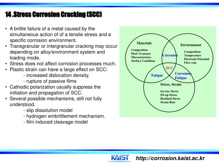
Materials. Environment. Composition Heat Treatment Microstructure Surface Condition. Composition Temperature Electrode Potential Flow rate. Corrosion. SCC. Corrosion- Fatigue. Fatigue. Stress, Strain. Service Stress Fit-up Stress Residual Stress Strain Rate.

E N D
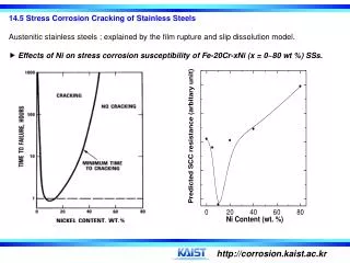
Materials Environment Composition Heat Treatment Microstructure Surface Condition Composition Temperature Electrode Potential Flow rate Corrosion SCC Corrosion- Fatigue Fatigue Stress, Strain Service Stress Fit-up Stress Residual Stress Strain Rate • 14 .Stress Corrosion Cracking (SCC) • A brittle failure of a metal caused by the simultaneous action of of a tensile stress and a specific corrosion environment. • Transgranular or intergranular cracking may occur depending on alloy/environment system and loading mode. • Stress does not affect corrosion processes much. • Plastic strain can have a large effect on SCC: - increased dislocation density. - rupture of passive films • Cathodic polarization usually suppress the initiation and propagation of SCC. • Several possible mechanisms, still not fully understood. - slip dissolution model- hydrogen embrittlement mechanism. • - film induced cleavage model
Stress No SCC SCC Strain
14. 2 How to evaluate the susceptibility to SCC A. Tests on statically loaded smooth specimens : Threshold stress(th) or critical cracking stress: - the max. stress below which SCC does not occur. - determined from the plot of applied stress vs. time to failure
Critical cracking potential (Ecc) • determined from the plot of applied potential vs. time to failure. • an electrochemical potential above which a metal will undergo SCC but below which a metal is protected from SCC. • The susceptibility to SCC in a particular environment is most clearly specified in terms of Ecc, and its relationship to the corrosion potential, Eoc. Specially, susceptibility to SCC exists in metal/environment systems in which Eocis noble to Ecc.
B. Tests on statically loaded precracked samples • Fracture mechanics testing for SCC provides more direct information on crack growth rate under known conditions of stress and defect depth. • Usually conducted with either a constant load or with a fixed crack opening displacement, and the da/dt is measured • The crack depth is determined as a function of time and the stress intensity is known from the crack depth and the load. K1SCC : the min. stress intensity below which SCC does not occur.
C. Slow strain rate tests(SSRT) or constant extension rate tests(CERT) A tensile machine pulls a smooth sample that is exposed to the corrosive environment at a slow cross head speed (10-5 - 10-9 m/s). The susceptibility to SCC for an alloy is compared in terms of the ratio of strain to failure in the corrosive environment to that in an inert environment.
1. Film breakdown by Cl- attack or emergency of slip steps 2. Formation of pit 3. Crack initiation & propagation Cathodic reaction on passive surface sustain anodic reactions within advancing cracks : 2H2O + 2e- 2OH- 1/2O2 + H2O + 2e- 2OH- H+ Cl- M+ Slip step . H2 Exits O2 OH- . Oxide Corrosion Products Cl- induced localized breakdown of passive film leads to corrosion pit e- Microcrack forms from corrosion pit when (H+) builds up (as below) e- Concomitant cathodic reduction of H+ leads to H entry into alloy : H+ + e- H(Fe)and H2 Anodic reaction within crack leads to high (H+) as : 2Cr + 3H2O Cr2O3 + 6H+ + 6e- H • 14.3 SCC Mechanisms • Many different mechanisms have been proposed to explain the synergistic stress-corrosion interaction that occurs at the crack tip, but still not fully understood. • A specific mechanism for SCC must attempt to explain the actual crack propagation rates, the fractographic evidence, and the mechanism of formation or nucleation of cracks. • The proposed mechanisms can be classed into two basic categories : • - Anodic mechanism : active dissolution, slip dissolution... • - Cathodic mechanism : hydrogen embrittlement.
A. Film rupture & Slip dissolution model • proposed for the transgranular cracking of austenitic stainless steels. According to this model, SCC occurs by repetitive processes of film breakdown/dissolution/repassivation. • Three dissolution modes are envisioned depending on the repassivation rate after film breakdown by the emergence of slip steps; • Mode 1 : repassivation is extremely rapid so that the amount of dissolution at the slip step is very small, • Mode 2 : an intermediate stage favoring cracking, • Mode 3 : repassivation rate is slow, giving rise to extensive lateral corrosion.
Repassivation kinetics and its relation to SCC (H. S. Kwon et al, Corrosion 56 (2000):32). • Repassivation rate : f(xalloy, [Cl-], T, E, crack tip) • For a given alloy/environment under constant loading condition, repassivation rate will determine SCC susceptibility. Film growth kinetics during repassivation. • Empirical law of passive film growth. : Decay gradient. • Theoretical models of passive film growth. - Place exchange model : - High field ion conduction model :
According to high field ion conduction model V : potential drop across film. h(t) : thickness of film.B : constant associated with ion movement. r : density of the film. M : molecular weight of the film. z : valence state. • from the high field • ion conduction model: • from theplace • exchange model: log i 1/Q log i -Q , slope : cBV
cBV as a measure of repassivation rate cBV(A) cBV(B) • Assume that aA= aB, and ip,A > ip,B. • For the same degree of repassivation rate, ir • - Repassivation time : tA > tB • Repassivation rate(Vr) : Vr,B > Vr,A - (cBV)A > (cBV)B : cBVRepassivation rate - Thickness of passive film, h(t) q(t) : q(tA) > q(tB) h(tA) > h(tB) An alloy with lower value of cBV is repassivated faster with formation of thinner and more protective film.
5000 4000 0 E = -54 mV -10 mV pit -100 -110 mV 3000 -200 Current density (mA/cm2) Potential(mV) Erp =-250 mV -210 mV -300 -310 mV 2000 -400 -510 mV -500 -3 -2 -1 0 1 2 3 10 10 10 10 10 10 10 1000 2 Current density ( m A/cm ) Increase of applied potential 0 0 100 200 300 400 500 Time (msec) Effects of Eapp on current transient after film breakdown -10 mV -110 mV
Effects of Eapp on SCC • Air, -310, -270 mV : • ductile dimple fracture. • -230 mV,-210 mV : • brittle fracture by quasi-cleavage. • -110 mV : fracture by severe • anodic dissolution. • Repassivation potential of -250 mV • is reasonable boundary between • ductile and brittle fracture. Air -230 mV -210 mV -270 mV, -310 mV SCC -110 mV No SCC severe dissolution
Type 304, 50 oC, 4 M NaCl solution. • 1st stage Eapp T cBVNo SCC [Cl-] • 2nd stage cBV : a limiting value • SCC • 3rd stage • Appearance of inflection point • Severe dissolution severe dissolution [H. S. Kwon et. al., Corrosion56 (2000), p. 32] CBV vs. SCC susceptibility
B. Brittle film rupture model or Film induced cleavage model - proposed explaining for SCC of copper or brass. C. Adsorption model - advocated for liquid metal embrittlement ; Adsorption of specific species reduces the surface energy , leading to a reduction in the stress required to produce brittle fracture.
D. Hydrogen embrittlement model Pulse loading experiments by Pugh A small load is superimposed on an otherwise constant load during crack propagation. As the frequency of loading was increased, the arrest marks on the fracture surface, which indicated at what point each pulse had been applied, became more closely spaced, but a minimum of 0.5 m mark separation distance was observed. The implication of this result was that the crack was proceeding by embrittling some volume of the steel ahead of the crack tip through which the crack then propagated rapidly.
▶ Loading Mode as a diagnostic tool The susceptibility of various alloys to environmentally induced embrittlement is found to be a function of the loading mode. Alloys sensitive to HE will be more susceptible to cracking in aqueous environment when loaded in tension (mode I) than when in torsion. Susceptivility of Ti-8Al-1Mo-1V to cracking in NaCl solutions under tensile and torsional loading. (after Green, et al.). Susceptibility of α-brass exposed to tarnishing ammoniacal solutions as a function of loading mode. (after Green, et al.).
Basis of the CEFM 1. Crack advance is assumed to occur via the slip dissolution/repassivation mechanism. 2. The internal and external environments are coupled by the charge conservation constraint; where, = net positive current emanating from the crack. = net cathodic current on the external surface. dS = increment in area on the external surface. E. Coupled Environment Fracture Model (D. D. Macdonald and Mirna Urquidi-Macdonald, Corrosion Sci., 2, 51, (1991)) Coupling of the internal and external environments by oxygen reduction on the external steel surfaces.
14. 4 SCC of High Strength Steels • SCC of high strength steels has all characteristics of hydrogen embrittlement(HE) : • The failure occurs by crack initiation and discontinuous propagation. • There is an incubation time for crack initiation(brittle delayed failure), prior to which time the damage is reversible by allowing the hydrogen to diffuse out(reversibility). • There is a preferred crack nucleation at crevices, notches, pits, pipe threads, welds. In fact, any discontinuity is a preferred location whether it be physical, chemical, or mechanical. • There is a critical yield strength below which brittle failure will not occur. • There is an applied stress below which failure will not occur. This critical(threshold) stress is primarily dependent on the yield strength, although it is sensitive to other parameters such as temperature and stress state. • The sensitivity to HE decreases from ambient up to 150 C for carbon and low alloy steel steels. • Cold work will increase the sensitivity to HE. • There is a synergistic effect between HE and any other type embrittlement that may present, such as, for example, temper embrittlement. All of these indicates that HE is the mechanism for SCC in high strength steels.
T.T.F Anodic polarization Cathodic polarization Ecorr H2 is evolved.( pH 10~12) H2 evolved in pit( pH 0~1) A. Phelps experimentSteel samples were polarized electrochemically from the corrosion potential during SCC test in 3% NaCl solution. The effect of anodic or cathodic polarization on the time to failure is shown below ; Phelps suggested that the failure in the anodic polarization branch is due to an anodic dissolution and the decrease in the time to failure with decreasing cathodic polarization was attributed to the HE. However,there was no difference in fracture surface for anodic or cathodic polarization. Pitting corrosion occurs during the anodic polarization. Therefore, H2 is being produced within the pits. Since some amount of cathodic polarization passivates some pits, the rate of hydrogen permeation decreases. Beyond some cathodic polarization level, hydrogen uptake increases. All of these suggest that both polarization branches are due to HE. anodic Polarization Branch Cathodic Polarization Branch
Yield Strength 110 ksi 90 ksi Y.S Break Points Time to failure B. NACE Tensile Test NACE Test is employed to determine the susceptibility to HE of high strength steels and conducted using a steel proof ring tester in a solution of 5% NaCl + 0.5% acetic acid( pH = 3.5) with hydrogen sulphide being continuously bubbled through the solution.Concept on the Yield Strength Break Point • Y. S. Break point :the yield strength at which failure will not occur in 30 days in the NACE tensile test when stressed to approximately 100% of its Y. S. (0.2% offset). • Threshold stress :the percent of the Y. S. below which SCC will not occur in 30 days in the NACE tensile test. This threshold stress rises as the Y. S. is reduced until eventually it becomes equal to the Y. S. Below this value, brittle delayed failure will not occur. • How to determine the Y. S. break point :Steel samples(for example 4135 steel) were quenched and tempered at different temperatures to produce various yield strength. Then, load of 100% of the Y. S. is applied to the specimen for 30 days in the NACE tensile test and measure the time to failure. The Y. S. break point is determined from the relationship between the yield strength and the time to failure.
Stress % of the Y.S. for samples having the Y.S. higher than yield strength break point Threshold stress : 30~40% of the Y.S. Time to failure Samples having the yield strength greater than the Y. S. break point are not fully safe to use under stresses near their Y. S. These samples has the threshold stresses of about 30 to 40% of their Y. S. Example) The Y. S. break point of AISI 4135 steel is found to be 100 ksi in the NACE tensile test. If this steel were tempered to have the Y.S. of 110ksi, it will be safe to use at stresses of 30 to 40% of the yield strength(33 to 44ksi), below which failure will not occur. Therefore, this alloy should be tempered to have the yield strength of max. 100 ksi. The Y. S. breakpoint exists in all high strength steels. In order to obtain best resistance to HE, the steels should be tempered to have yield strength below their Y.S. break point. The yield strength break point increases with decreasing the pH to 9 - 10 and also with increasing the temperature up to 425 F( consistent with an increased rate of hydrogen diffusion outward).