Download
1 / 6
60 likes | 66 Vues
Shear walls and outriggers have been used so far to resist the seismic waves of earthquake and heavy winds actions. The complete failure of the structures that has occurred in the past due to catastrophic earthquake may be avoided with the use of shear wall in the structure. The study is concerned with the use of shear wall as a single core in structure that will resist the seismic waves of earthquake. In the present study analysis of RCC building has been carried out by changing the locations of shear walls in the building. The seismic analysis performed is linear dynamic response spectrum analysis using the well known analysis and design software ETABS 16.2.0. Seismic performance of the building has been investigated based on parameters such as strorey drift, base shear and storey displacement. Belsare Sumit Bandopanth | Dilip Budhlani "Seismic Response of Structure with Single Core" Published in International Journal of Trend in Scientific Research and Development (ijtsrd), ISSN: 2456-6470, Volume-4 | Issue-3 , April 2020, URL: https://www.ijtsrd.com/papers/ijtsrd30851.pdf Paper Url :https://www.ijtsrd.com/engineering/civil-engineering/30851/seismic-response-of-structure-with-single-core/belsare-sumit-bandopanth<br>

E N D
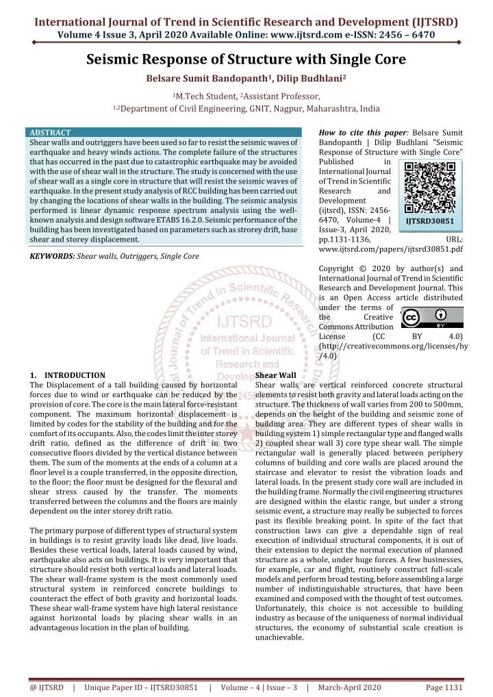
International Journal of Trend in Scientific Research and Development (IJTSRD) Volume 4 Issue 3, April 2020 Available Online: www.ijtsrd.com e-ISSN: 2456 – 6470 Seismic Response of Structure with Single Core Belsare Sumit Bandopanth1, Dilip Budhlani2 1M.Tech Student, 2Assistant Professor, 1,2Department of Civil Engineering, GNIT, Nagpur, Maharashtra, India ABSTRACT Shear walls and outriggers have been used so far to resist the seismic waves of earthquake and heavy winds actions. The complete failure of the structures that has occurred in the past due to catastrophic earthquake may be avoided with the use of shear wall in the structure. The study is concerned with the use of shear wall as a single core in structure that will resist the seismic waves of earthquake. In the present study analysis of RCC building has been carried out by changing the locations of shear walls in the building. The seismic analysis performed is linear dynamic response spectrum analysis using the well- known analysis and design software ETABS 16.2.0. Seismic performance of the building has been investigated based on parameters such as strorey drift, base shear and storey displacement. KEYWORDS: Shear walls, Outriggers, Single Core How to cite this paper: Belsare Sumit Bandopanth | Dilip Budhlani "Seismic Response of Structure with Single Core" Published in International Journal of Trend in Scientific Research and Development (ijtsrd), ISSN: 2456- 6470, Volume-4 | Issue-3, April 2020, pp.1131-1136, www.ijtsrd.com/papers/ijtsrd30851.pdf Copyright © 2020 by author(s) and International Journal of Trend in Scientific Research and Development Journal. This is an Open Access article distributed under the terms of the Creative Commons Attribution License (CC (http://creativecommons.org/licenses/by /4.0) IJTSRD30851 URL: BY 4.0) 1.INTRODUCTION The Displacement of a tall building caused by horizontal forces due to wind or earthquake can be reduced by the provision of core. The core is the main lateral force-resistant component. The maximum horizontal displacement is limited by codes for the stability of the building and for the comfort of its occupants. Also, the codes limit the inter storey drift ratio, defined as the difference of drift in two consecutive floors divided by the vertical distance between them. The sum of the moments at the ends of a column at a floor level is a couple transferred, in the opposite direction, to the floor; the floor must be designed for the flexural and shear stress caused by the transfer. The moments transferred between the columns and the floors are mainly dependent on the inter storey drift ratio. The primary purpose of different types of structural system in buildings is to resist gravity loads like dead, live loads. Besides these vertical loads, lateral loads caused by wind, earthquake also acts on buildings. It is very important that structure should resist both vertical loads and lateral loads. The shear wall-frame system is the most commonly used structural system in reinforced concrete buildings to counteract the effect of both gravity and horizontal loads. These shear wall-frame system have high lateral resistance against horizontal loads by placing shear walls in an advantageous location in the plan of building. Shear Wall Shear walls are vertical reinforced concrete structural elements to resist both gravity and lateral loads acting on the structure. The thickness of wall varies from 200 to 500mm, depends on the height of the building and seismic zone of building area. They are different types of shear walls in building system 1) simple rectangular type and flanged walls 2) coupled shear wall 3) core type shear wall. The simple rectangular wall is generally placed between periphery columns of building and core walls are placed around the staircase and elevator to resist the vibration loads and lateral loads. In the present study core wall are included in the building frame. Normally the civil engineering structures are designed within the elastic range, but under a strong seismic event, a structure may really be subjected to forces past its flexible breaking point. In spite of the fact that construction laws can give a dependable sign of real execution of individual structural components, it is out of their extension to depict the normal execution of planned structure as a whole, under huge forces. A few businesses, for example, car and flight, routinely construct full-scale models and perform broad testing, before assembling a large number of indistinguishable structures, that have been examined and composed with the thought of test outcomes. Unfortunately, this choice is not accessible to building industry as because of the uniqueness of normal individual structures, the economy of substantial scale creation is unachievable. @ IJTSRD | Unique Paper ID – IJTSRD30851 | Volume – 4 | Issue – 3 | March-April 2020 Page 1131
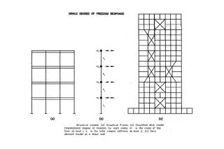
International Journal of Trend in Scientific Research and Development (IJTSRD) @ www.ijtsrd.com eISSN: 2456-6470 columns to assist in restraining the outriggers. This is achieved by including a deep Spandrel Girder, or a Belt Truss, around the structure at the levels of the outriggers. To make the Outriggers and Belt Truss adequately stiff in flexure and shear, they are made at least one, and often 2 – stories deep. It is also possible to use diagonals extending through several floors to act as outriggers. And finally, girders at each floor may be transformed into outriggers by moment connections to the core and, if desired, to the exterior columns as well. Here, it should be noted that while the outrigger system is very effective in increasing the structure’s flexural stiffness, it doesn’t increase its resistance to shear, which has to be carried mainly by the core. Figure 1 Types of shear walls Outriggers Although outriggers have been used for approximately four decades, their existence as a structural member has a much longer history. Outriggers have been used in the sailing ship industry for many years. They are used to resist wind. The slender mast provides the use of outriggers. As a comparison the core can be related to the mast, the outriggers are like the spreaders and the exterior columns are like the shrouds or stays. Innovative structural schemes are continuously being sought in the field. Structural Design of High-Rise Structures with the intention of limiting the Drift due to Lateral Loads to acceptable limits without paying a high premium in steel tonnage. The savings in steel tonnage and cost can be dramatic if certain techniques are employed to utilize the full capacities of the structural elements. Various wind bracing techniques have been developed in this regard; one such is an Outrigger System, in which the axial stiffness of the peripheral columns is invoked for increasing the resistance to overturning moments. This efficient structural form consists of a central core, comprising either Braced Frames or Shear Walls, with horizontal cantilever trusses or girders known as outrigger Trusses, connecting the core to the outer columns. The core may be centrally located with outriggers extending on both sides (Fig.2.a) or it may be located on one side of the building with outriggers extending to the building columns on one side (Fig.2.b). (C) Fig.3 Diagonals acting as outriggers 2.CASE STUDY Study is carried out by Modeling of the G+20 storey buildings with core shear wall and braced core at center, corner and side in ETABS 2016. During the analysis various IS codes have been adopted such as IS: 456 for concrete design, IS: 875 for loads, IS: 800 for steel design, IS: 1893-2016 for seismic design. The seismic effect on the structure has been studied using response spectrum method and corresponding various parameters has been tabulated. The main seismic parameters that are compared are maximum displacement, storey drift, base shear, time period and axial force and moments in columns. The following various parameters were considered for modelling and Analysis of the structure in ETABS. Building Plan and its Geometry The plan area of the building is kept 21 m x 21 m. Height of each storey is kept uniform i.e. 3 m. so the total height of the building is 63m. Number of bay in x direction is 5 and Number of bay in y direction is 5, the bay width in x direction is 4.2 m, the bay width in y direction is 4.2m. Various type of structural model considered for this study. ?Model 1- Symmetric plan frame without center core. ?Model 2- Symmetric plan frame without corner core. ?Model 3- Symmetric plan frame without side core. ?Model 4- Symmetric plan frame with center shear wall (SW) core. ?Model 5- Symmetric plan frame with corner shear wall (SW) core. ?Model 6- Symmetric plan frame with side shear wall (SW) core. Fig.2 (a) Outrigger system with a central core (b) Outrigger system with offset core When Horizontal loading acts on the building, the column restrained outriggers resist the rotation of the core, causing the lateral deflections and moments in the core to be smaller than if the free-standing core alone resisted the loading. The result is to increase the effective depth of the structure when it flexes as a vertical cantilever, by inducing tension in the windward columns and Compression in the leeward columns. In addition to those columns located at the ends of the outriggers, it is usual to also mobilize other peripheral @ IJTSRD | Unique Paper ID – IJTSRD30851 | Volume – 4 | Issue – 3 | March-April 2020 Page 1132
International Journal of Trend in Scientific Research and Development (IJTSRD) @ www.ijtsrd.com eISSN: 2456-6470 ?Model 7- Symmetric plan frame with center braced (BR) core. ?Model 8- Symmetric plan frame with corner braced (BR) core. ?Model 9- Symmetric plan frame with side braced (BR) core. ?Model 10- Asymmetric plan frame without center core. ?Model 11- Asymmetric plan frame without corner core. ?Model 12- Asymmetric plan frame without side core. ?Model 13- Asymmetric plan frame with center shear wall (SW) core. ?Model 14- Asymmetric plan frame with corner shear wall (SW) core. ?Model 15- Asymmetric plan frame with side shear wall (SW) core. ?Model 16- Asymmetric plan frame with center braced (BR) core. ?Model 17- Asymmetric plan frame with corner braced (BR) core. ?Model 18- Asymmetric plan frame with side braced (BR) core. ?Model 19- Asymmetric L plan frame without center core. ?Model 20- Asymmetric L plan frame without corner core. ?Model 21- Asymmetric L plan frame without side core. ?Model 22- Asymmetric L plan frame with center shear wall (SW) core. ?Model 23- Asymmetric L plan frame with corner shear wall (SW) core. ?Model 24- Asymmetric L plan frame with side shear wall (SW) core. ?Model 25- Asymmetric L plan frame with center braced (BR) core. ?Model 26- Asymmetric L plan frame with corner braced (BR) core. ?Model 27- Asymmetric L plan frame with side braced (BR) core. Material properties Concrete of grade M35, steel grade of Fe 345 and Rebar of grade Fe500 is used for modeled the building. The poison’s ratio for concrete and steel is taken as 0.3. The density of concrete is 25kN/m³ and density of brick masonry is 20 KN/m3 is considered for modeled the building. Member dimensions The dimensions of members are decided by observing the stability aspect table 1 shows the member dimensions which have used in all models of building. Table 1 Member Dimensions Member Thickness of RCC Slab Beam Size Column Size Thickness of Brick Masonry wall Thickness of RCC Shearwall Steel Outriggers Load details Following are the details of loads which has considered in this analysis and design of Building. A. Dead load: - In ETABS the software itself calculates the dead loads by applying a self-weight multiplier factor of one which is taken by the structure and the rest load cases are kept zero. Its defined in the load patterns section. Live load on floors: - 2.5 KN/m² as per IS:875 (part -2). Live load on roof: - 1.5 KN/m² as per IS:875 (part -2). Wall load on all levels: - 3 x 0.23 x 20 = 11.5 KN/m. B. C. D. Seismic Data Zone Factor: - Zone III (0.16) Importance factor: - 1.2 (Residential building with occupancy more than 200 persons) Response Reduction Factor: - 5 Special moment resisting frame (SMRF) Soil Type: - II Medium Damping Ratio: - 5% Load Combinations Each model of the building is subjected to Dead Load, Live Load and Seismic Forces in – (+) X and (-) X Direction (+) Y and (-) Y Direction After applying above load each model of the building is analyzed for dynamic method under the following load combination generated automatically using ETABS: - ? 1.5 x [DL-Self Weight] ? 1.5 x [DL + LL] ? 1.2 x [DL + LL + EQX] ? 1.2 x [DL + LL - EQX] ? 1.2 x [DL + LL + EQX-] ? 1.2 x [DL + LL – EQX-] ? 1.2 x [DL + LL + EQY] ? 1.2 x [DL + LL - EQY] ? 1.2 x [DL + LL + EQY-] ? 1.2 x [DL + LL – EQY-] ? 1.5 x [DL + EQX] ? 1.5 x [DL - EQX] ? 1.5 x [DL + EQX-] ? 1.5 x [DL - EQX-] ? 1.5 x [DL + EQY] ? 1.5 x [DL - EQY] ? 1.5 x [DL + EQY-] ? 1.5 x [DL - EQY-] ? 0.9 DL + 1.5 EQX ? 0.9 DL - 1.5 EQX ? 0.9 DL + 1.5 EQX- ? 0.9 DL - 1.5 EQX- ? 0.9 DL + 1.5 EQY ? 0.9 DL - 1.5 EQY ? 0.9 DL + 1.5 EQY ? 0.9 DL - 1.5 EQY 3.METHODOLOGY OF PROPOSED WORK A.Modeling of the twenty storey buildings with core shear wall and braced core at center, corner and side in ETABS. B.Application of gravity loads (dead, live, wall load) as per Indian codes and lateral loads as per IS 1893:2002. Since the live load class is up to 3 KN/m2, 25% of the imposed load has been considered. C.Analyzing the building using Response spectrum analysis with fixed support. D.Comparing the results of building models. Size 150 mm 230 mm x 500 mm 600 mm x 600 mm 230 mm 250 mm ISA 150 x 150 x 15 mm @ IJTSRD | Unique Paper ID – IJTSRD30851 | Volume – 4 | Issue – 3 | March-April 2020 Page 1133
International Journal of Trend in Scientific Research and Development (IJTSRD) @ www.ijtsrd.com eISSN: 2456-6470 4.MODELLING General In this study, total twenty-seven models are considered to perform the seismic analysis. All the models having 20 stories and height of each storey was 3m. First nine models are in the square plan of 21m x 21m with 5 bays on each side and the next eighteen models are asymmetric in plan. In all the models the lateral loads are resisted by with and without single core (SW & BR) with varying position of core. Response spectrum method of seismic analysis is carried out as per IS 1893:2016. Modeling and analysis are done in ETABS software. Response Spectrum Analysis Earthquake engineers preferred to report an interaction between the acceleration of ground and structural system through response spectrum first proposed by Biot and later popularized by Housner. A Response spectrum is a plot of the maximum response of a set of SDOF systems subjected to ground motion as ordinate and corresponding time periods of the SDOF system as abscissa. This method is applicable for those structures where modes other than the basic mode that influences the structure reaction. In this method the Multi-degree-of-Freedom (MDOF) system response is expressed as the superposition of modal response, by the spectral analysis of single-degree-of-freedom (SDOF) system, the response of each mode being determined, which are then combined to find out the total response. Methods of combining modal response: A. Absolute – peak values are added together B. Square root of the sum of the squares (SRSS) C. Complete quadratic combination (CQC) Fig.6 Model 2- Symmetric plan frame without corner core Fig.7 Model 3 - Symmetric plan frame without side core Fig.4 Response Spectrum Curve Fig.8 Model 4 - symmetric plan frame with center shear wall (SW) core. Building Models Fig.5 Model 1- Symmetric plan frame without center core Fig.9 Model 5 - symmetric plan frame with corner shear wall (SW) core. @ IJTSRD | Unique Paper ID – IJTSRD30851 | Volume – 4 | Issue – 3 | March-April 2020 Page 1134
International Journal of Trend in Scientific Research and Development (IJTSRD) @ www.ijtsrd.com eISSN: 2456-6470 Fig. 10 Model 6 - symmetric plan frame with side shear wall (SW) core. Fig.14 Model 13 - Asymmetric plan frame with center shear wall (SW) core Fig.15 Model 14 - Asymmetric plan frame with corner shear wall (SW) core Fig. 11 Model 10 – Asymmetric plan frame without center core. Fig. 16 Model 15 - Asymmetric plan frame with side shear wall (SW) core. Fig.12 Model 11 -Asymmetric plan frame without corner core. Fig.13 Model 12 - Asymmetric plan frame without side core. Fig.17 Model 19 - Asymmetric L plan frame without center core. @ IJTSRD | Unique Paper ID – IJTSRD30851 | Volume – 4 | Issue – 3 | March-April 2020 Page 1135
International Journal of Trend in Scientific Research and Development (IJTSRD) @ www.ijtsrd.com eISSN: 2456-6470 Fig.22 Model 24 - Asymmetric L plan frame with side shear wall (SW) core. Fig.18 Model 20 - Asymmetric L plan frame without corner core. 5.CONCLUSION Satisfying the requirement of the stability conditions for a single core structure will be complicated one, compared with the structures supported in all sides depending upon their configuration. Single core structure is a critical one when it is subjected to unsymmetrical and eccentric loading conditions. Eccentric loading will cause the structure to twist in any direction and may cause failure of structure. By the study, we want to explore a new dimension of the existing construction techniques. This study describes planning, structural analysis and design of the single core building. The Buildings with single core at corner and side position tends to go in Torsion Mode which develops extra forces in the frames. Greater Economy can be achieved by keeping the single Cores at Centre of the Buildings. Building at center core will gives economical design as well as sufficient amount of safety. 6.REFERENCE [1]IS: 1893 PART 1 (2016) “Criteria for Earthquake Resistant Design of Structures – general provisions and buildings” Bureau of Indian Standards, New Delhi. Fig.19 Model 21 - Asymmetric L plan frame without side core. [2]Jibi Abraham “Seismic Analysis Of Pyramid Shaped Building With And Without Bracing” , published in International Research Journal of Engineering and Technology (IRJET) Volume: 05 Issue: 05 | May-2018, ISSN: 2395-0056 [3]Maikesh Chouhan, ‘Dynamic Analysis of Multi-Storeyed Frame-Shear Wall Building Considering SSI’, published in International Journal of Engineering Research and Application Vol. 6, Issue 8, ( Part -1) August 2016, pp.31-35 www. ijera.com ISSN : 2248-9622 Fig.20 Model 22 - Asymmetric L plan frame with center shear wall (SW) core. [4]Pavan Kumar, ‘Earthquake Analysis of Multi Storied Residential Building - A Case Study’, published in International Journal of Engineering Research and Applications www.ijera.com, Vol. 4, Issue 11( Version 1), November 2014, pp.59-64, ISSN : 2248-9622 [5]Abrar Ahmed, ‘Seismic Analysis On Building With Horizontal And Vertical Irregularities’, published in International Journal of Advance Engineering and Research Development Volume 4, Issue 9, September - 2017 Fig.21 Model 23 - Asymmetric L plan frame with Corner shear wall (SW) core. @ IJTSRD | Unique Paper ID – IJTSRD30851 | Volume – 4 | Issue – 3 | March-April 2020 Page 1136