Download
1 / 5
50 likes | 55 Vues
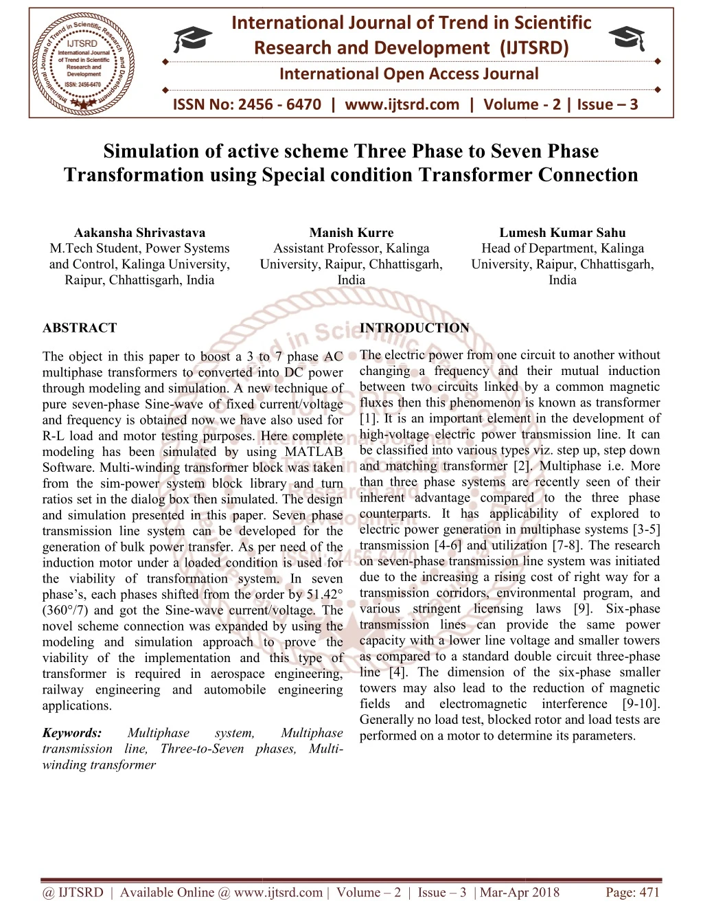
The object in this paper to boost a 3 to 7 phase AC multiphase transformers to converted into DC power through modeling and simulation. A new technique of pure seven phase Sine wave of fixed current voltage and frequency is obtained now we have also used for R L load and motor testing purposes. Here complete modeling has been simulated by using MATLAB Software. Multi winding transformer block was taken from the sim power system block library and turn ratios set in the dialog box then simulated. The design and simulation presented in this paper. Seven phase transmission line system can be developed for the generation of bulk power transfer. As per need of the induction motor under a loaded condition is used for the viability of transformation system. In seven phase's, each phases shifted from the order by 51.42u00c2u00b0 360u00c2u00b0 7 and got the Sine wave current voltage. The novel scheme connection was expanded by using the modeling and simulation approach to prove the viability of the implementation and this type of transformer is required in aerospace engineering, railway engineering and automobile engineering applications. Aakansha Shrivastava | Manish Kurre | Lumesh Kumar Sahu "Simulation of active scheme Three Phase to Seven Phase Transformation using Special condition Transformer Connection" Published in International Journal of Trend in Scientific Research and Development (ijtsrd), ISSN: 2456-6470, Volume-2 | Issue-3 , April 2018, URL: https://www.ijtsrd.com/papers/ijtsrd10801.pdf Paper URL: http://www.ijtsrd.com/engineering/electrical-engineering/10801/simulation-of-active-scheme-three-phase-to-seven-phase-transformation-using-special-condition-transformer-connection/aakansha-shrivastava<br>

E N D
International Research Research and Development (IJTSRD) International Open Access Journal Simulation of active scheme Three Phase to Seven Phase Transformation using Special condition Transformer Connection Transformation using Special condition Transformer Connection International Journal of Trend in Scientific Scientific (IJTSRD) International Open Access Journal ISSN No: 2456 ISSN No: 2456 - 6470 | www.ijtsrd.com | Volume 6470 | www.ijtsrd.com | Volume - 2 | Issue – 3 Simulation of active scheme Three Phase to Seven Phase Transformation using Special condition Transformer Connection Simulation of active scheme Three Phase to Seven Phase Aakansha Shrivastava M.Tech Student, Power Systems and Control, Kalinga University, Raipur, Chhattisgarh, India Manish Kurre Assistant Professor, Kalinga Lumesh Kumar Sahu Head of Department, University, Raipur, Chhattisgarh, University, Raipur, Chhattisgarh, India Lumesh Kumar Sahu Head of Department, Kalinga University, Raipur, Chhattisgarh, University, Raipur, Chhattisgarh, India ABSTRACT The object in this paper to boost a 3 to 7 phase AC multiphase transformers to converted into DC power through modeling and simulation. A new technique of pure seven-phase Sine-wave of fixed current/voltage and frequency is obtained now we have also used f R-L load and motor testing purposes. Here complete modeling has been simulated by using MATLAB Software. Multi-winding transformer block was taken from the sim-power system block library and turn ratios set in the dialog box then simulated. The design and simulation presented in this paper. Seven phase transmission line system can be developed for the generation of bulk power transfer. As per need of the induction motor under a loaded condition is used for the viability of transformation system. In seven phase’s, each phases shifted from the order by 51.42° (360°/7) and got the Sine-wave current/voltage. The novel scheme connection was expanded by using the modeling and simulation approach to prove the viability of the implementation and this type of transformer is required in aerospace engineering, railway engineering and automobile engineering applications. INTRODUCTION The electric power from one circuit to another without changing a frequency and their mutual induction between two circuits linked by a common magnetic fluxes then this phenomenon is known as transformer [1]. It is an important element in the development of high-voltage electric power transmission line. It can be classified into various types viz. step up, step down and matching transformer [2]. Multiphase i.e. More than three phase systems are recently seen of their inherent advantage compared to the three phase counterparts. It has applicability of explored to electric power generation in multiphase systems [3 transmission [4-6] and utilization [7 on seven-phase transmission line system was initiated due to the increasing a rising cost of right way for a transmission corridors, environmental program, and various stringent licensing laws [9]. Six transmission lines can provide the same power capacity with a lower line voltage and smaller towers as compared to a standard double circuit three line [4]. The dimension of the six towers may also lead to the reduction of magnetic fields and electromagnetic interference [9 Generally no load test, blocked rotor and load tests are performed on a motor to determine its parameters. performed on a motor to determine its parameters. one circuit to another without The object in this paper to boost a 3 to 7 phase AC multiphase transformers to converted into DC power through modeling and simulation. A new technique of wave of fixed current/voltage and frequency is obtained now we have also used for L load and motor testing purposes. Here complete modeling has been simulated by using MATLAB winding transformer block was taken power system block library and turn ratios set in the dialog box then simulated. The design nd simulation presented in this paper. Seven phase transmission line system can be developed for the generation of bulk power transfer. As per need of the induction motor under a loaded condition is used for the viability of transformation system. In seven phase’s, each phases shifted from the order by 51.42° wave current/voltage. The novel scheme connection was expanded by using the modeling and simulation approach to prove the viability of the implementation and this type of sformer is required in aerospace engineering, railway engineering and automobile engineering changing a frequency and their mutual induction between two circuits linked by a common magnetic fluxes then this phenomenon is known as transformer [1]. It is an important element in the development of power transmission line. It can be classified into various types viz. step up, step down and matching transformer [2]. Multiphase i.e. More than three phase systems are recently seen of their inherent advantage compared to the three phase has applicability of explored to electric power generation in multiphase systems [3-5] 6] and utilization [7-8]. The research phase transmission line system was initiated due to the increasing a rising cost of right way for a mission corridors, environmental program, and various stringent licensing laws [9]. Six-phase transmission lines can provide the same power capacity with a lower line voltage and smaller towers as compared to a standard double circuit three-phase The dimension of the six-phase smaller towers may also lead to the reduction of magnetic fields and electromagnetic interference [9-10]. Generally no load test, blocked rotor and load tests are Keywords: transmission line, Three-to-Seven phases, Multi winding transformer Multiphase Multiphase system, system, Seven phases, Multi- Multiphase Multiphase @ IJTSRD | Available Online @ www.ijtsrd.com @ IJTSRD | Available Online @ www.ijtsrd.com | Volume – 2 | Issue – 3 | Mar-Apr 2018 Apr 2018 Page: 471
International Journal of Trend in Scientific Research and Development (IJTSRD) ISSN: 2456 International Journal of Trend in Scientific Research and Development (IJTSRD) ISSN: 2456 International Journal of Trend in Scientific Research and Development (IJTSRD) ISSN: 2456-6470 Fig. 1 Block diagram representation Fig. 1 Block diagram representation of the proposed system of the proposed system We know that multi-phase motors are invariably supplied by ac/dc/ac converters. The multiphase electric drive is limited for the modeling and controls the supply systems [14]. Our main objective is to develop static transformation system to change the phase number from three to seven (where n>3). Now we are generating a novel phase transformation system which convert three phase to a seven supply [15]. In multiphase system six phases and twelve phases is found to produce fewer ripples with a high frequency in an AC-DC rectifier system. Thus six and twelve phase transformers are designed to feed a number of pulses rectifier system and technology has matured [13]. Now, twenty four phase and thirty six phase transformer systems have proposed for supplying a number of pulse rectifier systems [12-16]. These designs are also available for an odd number of phases, such as five, nine and eleven etc. In this paper we have proposed a special transformer connection scheme to get a seven output supply from three-phase. The expected applications of the power transformer are the electric power transmission system and power electronic converters and the multiphase electric drive system. The block represented of the proposed system is shown in figure 1.The fixed voltage and fixed frequency available grid supply can be transformed to the fixed frequency seven-phase output supply. The output may be made variable by inserting the autotransformer at the primary side. The input and output supply can be arranged in the f manner [20] as below. Input Star, Output Star. Input manner [20] as below. Input Star, Output Star. Input phase motors are invariably Star, Output heptagon. Input Delta, Output Star. Input Delta, Output heptagon. The input has being three- phase system the windings are connected in a usually fashion. The (seven phase) heptagon output connection may be derived following a similar approach. The output/secondary side connection is Star, Output heptagon. Input Delta, Output Star. Input Delta, Output heptagon. The input has being three phase system the windings are connected in a usually fashion. The (seven phase) heptagon connection may be derived following a similar approach. The output/secondary side connection is discussed in the following subsections. discussed in the following subsections. supplied by ac/dc/ac converters. The multiphase electric drive is limited for the modeling and controls the supply systems [14]. Our main objective is to develop static transformation system to change the e number from three to seven (where n>3). Now we are generating a novel phase transformation system which convert three phase to a seven-phase supply [15]. In multiphase system six phases and twelve phases is found to produce fewer ripples with a DC rectifier system. Thus six and twelve phase transformers are designed to feed a number of pulses rectifier system and technology has matured [13]. Now, twenty four phase and thirty six phase transformer systems have a number of pulse rectifier 16]. These designs are also available for an odd number of phases, such as five, nine and eleven etc. In this paper we have proposed a special transformer connection scheme to get a seven-phase WINDING ARRANGEMENT FOR SEVEN- WINDING ARRANGEMENT FOR SEVEN PHASE STAR OUTPUT Three separate iron cores are designed with each of g one primary and four secondary coils, except in one core where five secondary coils are wound. Six terminals of primaries are connected in an appropriate manner resulting in star and/or delta connections, and the 26 terminals of secondaries are in a different fashion resulting in a star or heptagon output. The connection scheme of secondary windings to obtain star output is illustrated in Figs. 1 and 2 and the corresponding phasor diagram is illustrated in Fig. 3. The construction of output phases with requisite phase angles of 360/7 = 51.43◦ between each phase is obtained using appropriate turn ratios and the governing phasor equation is illustrated in (1c). The turn ratios are different in each phase as shown in Fig. 1. The choice of turn ratio is the key in creating the requisite phase displacement in the output phases. The turn ratios between different phases are given in Table I. The input phases are designated with letters “X,” “Y,” and “Z” and the output are designated with letters “a,” “b,” “c,” “d,” “e,” “f,” and Three separate iron cores are designed with each of them carrying one primary and four secondary coils, except in one core where five secondary coils are wound. Six terminals of primaries are connected in an appropriate manner resulting in star and/or delta connections, and the 26 terminals of secondaries are connected in a different fashion resulting in a star or heptagon output. The connection scheme of secondary windings to obtain star output is illustrated in Figs. 1 and 2 and the corresponding phasor diagram is illustrated in Fig. 3. The construction of output phas with requisite phase angles of 360/7 = 51.43 each phase is obtained using appropriate turn ratios and the governing phasor equation is illustrated in (1c). The turn ratios are different in each phase as shown in Fig. 1. The choice of turn ratio creating the requisite phase displacement in the output phases. The turn ratios between different phases are given in Table I. The input phases are designated with letters “X,” “Y,” and “Z” and the output are designated with letters “a,” “b, “g.” phase. The expected applications of the power transformer are the electric power transmission system and power electronic converters and the multiphase electric drive system. The block represented of the proposed system is oltage and fixed frequency available grid supply can be transformed to phase output supply. The output may be made variable by inserting the autotransformer at the primary side. The input and output supply can be arranged in the following @ IJTSRD | Available Online @ www.ijtsrd.com @ IJTSRD | Available Online @ www.ijtsrd.com | Volume – 2 | Issue – 3 | Mar-Apr 2018 Apr 2018 Page: 472
International Journal of Trend in Scientific Research and Development (IJTSRD) ISSN: 2456 International Journal of Trend in Scientific Research and Development (IJTSRD) ISSN: 2456 International Journal of Trend in Scientific Research and Development (IJTSRD) ISSN: 2456-6470 Fig. 2 Proposed transformer winding star Fig. 2 Proposed transformer winding star-star connection Fig. 3 (A) A new schematic diagram of a three phase to seven phases “star secondary windings and (B) secondary windings and (B) Phasor diagram of the transformer connection (star Phasor diagram of the transformer connection (star-star) . Fig. 3 (A) A new schematic diagram of a three phase to seven phases “star-star” power transformer with star” power transformer with Fig. 5 (A) A new schematic diagram of a three phase to seven phases “delta Fig. 5 (A) A new schematic diagram of a three phase to seven phases “delta-star” power transformer with secondary windings star” power transformer @ IJTSRD | Available Online @ www.ijtsrd.com @ IJTSRD | Available Online @ www.ijtsrd.com | Volume – 2 | Issue – 3 | Mar-Apr 2018 Apr 2018 Page: 473
International Journal of Trend in Scientific Research and Development (IJTSRD) ISSN: 2456-6470 run. The resulting input and output voltage and current waveform are given in star-star and for delta- star. The output will be unbalance if input is unbalanced and also if the input is balance then output is also balance. The three phase output from a seven phase input supply can also be obtain in similar fashion. STIMULATION RESULTS The new designed/modeling is the first using “Sim power system” block set of the MATLAB/Simulink software. Multiwinding transformer block is chosen from the sim-power system block library and the turn ratios are set in the dialog box and the simulation is 1.Matlab model 2.Output waveform @ IJTSRD | Available Online @ www.ijtsrd.com | Volume – 2 | Issue – 3 | Mar-Apr 2018 Page: 474
International Journal of Trend in Scientific Research and Development (IJTSRD) ISSN: 2456-6470 8.J. R. Stewart, E. Kallaur, and J. S. Grant, “Economics of EHV transmission,” IEEE Trans. Power App. Syst., vol. -PAS 103, no. 11, pp. 3386–3392, Nov. 1984. CONCLUSION high phase order This paper proposes a new transformer connection scheme to transform the three-phase grid power to a seven-phase output supply. The connection scheme and the phasor diagram, along with the turn ratios, are illustrated. The successful implementation of the proposed connection scheme is elaborated upon using both simulation and experimentation. It is expected that the proposed connection scheme can be used in drives and other multiphase applications, e.g., ac–ac and dc–ac power conversion systems 9.S. N. Tewari, G. K. Singh, and A. B. Saroor, “Multiphase Power transmission research—A survey,” Electr. Power Syst. Res., vol. 24, pp. 207–215, 1992. 10.C. M. Portela and M. C. Tavares, “Six-phase transmission line-propagation characteristics and new three-phase representation,” IEEE Trans. Power Delivery, vol. 18, no. 3, pp. 1470–1483, Jul. 1993. REFERENCES 1.D. Basic, J. G. Zhu, and G. Boardman, “Transient performance study of brushless doubly fed twin stator generator,” IEEE Trans. Energy Convers., vol. 18, no. 3, pp. 400–408, Sep. 2003. 11.T. L. Landers, R. J. Richeda, E. Krizanskas, J. R. Stewart, and R. A. Brown, “High phase order economics: Constructing a new transmission line,” IEEE Trans. Power Delivery, vol. 13, no. 4, pp. 1521–1526, Oct. 1998. 2.G. K. Singh, “Self excited induction generator research—A survey,” Elect. Power Syst. Res., vol. 69, pp. 107–114, 2004. 3.O. Ojo and I. E. Davidson, “PWM-VSI inverter- assisted stand-alone dual stator winding induction generator,” IEEE Trans. Energy Convers., vol. 36, no. 6, pp. 1604–1611, Nov./Dec. 2000. 4.G. K. Singh, K. B. Yadav, and R. P Sani, “Analysis of saturated multiphase (six-phase) self excited induction generator,” Int J. Emerg. Electr.Power Syst., vol. 7, no. 2, article 5, Sep. 2006. 5.G. K. Singh, “Modelling and experimental analysis of a self excitedsixphase induction generator for stand alone renewable energy generation,” Renewable Energy, vol. 33, no. 7, pp. 1605–162, Jul. 2008. 6.J. R. Stewart and D. D. Wilson, “High phase order transmission—A feasibility Steady state considerations,” IEEE Trans. Power App. Syst., vol. PAS-97, no. 6, pp. 2300–2307, Nov. 1978. analysis—Part-I: 7.J. R. Stewart and D. D. Wilson, “High phase order transmission- A feasibility analysis—Part-II: Over voltages and insulation requirements,” IEEE Trans. Power App. Syst., vol. PAS-97, no. 6, pp. 2308–2317, Nov. 1978. @ IJTSRD | Available Online @ www.ijtsrd.com | Volume – 2 | Issue – 3 | Mar-Apr 2018 Page: 475