Download
1 / 4
40 likes | 64 Vues
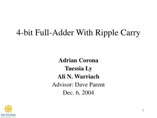
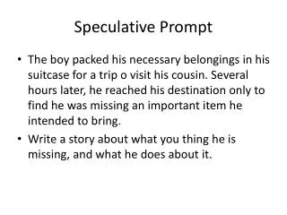
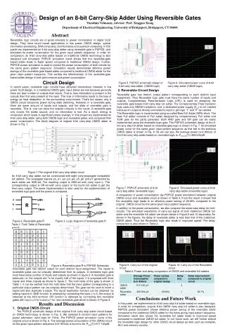
Arithmetic logic units and digital signal processors widely uses adders. It is the most complicated arithmetic circuits in digital electronics. The existing adders suffer from critical path delay, area overhead and power consumption. Speculative adders are designed with variable latency that combines speculation technique along with correction methodology to attain high performance in terms of low area overhead over the existing adders. In speculative adders the sum and carry generation part is separated to reduce the area overhead. Carry Speculative Adder CSPA uses carry predictor circuit to reduce power consumption and to reduce the computational time and it uses error recognition and error correction circuit to find the fault occurred in the partial sum generator and to recover it to get accurate results. B. V. Pavan Kumar | M. Lalitha Bhavani | Y. Himanth "Optimized Carry Speculative Adder" Published in International Journal of Trend in Scientific Research and Development (ijtsrd), ISSN: 2456-6470, Volume-2 | Issue-3 , April 2018, URL: https://www.ijtsrd.com/papers/ijtsrd11216.pdf Paper URL: http://www.ijtsrd.com/engineering/electronics-and-communication-engineering/11216/optimized-carry-speculative-adder/b-v-pavan-kumar<br>

E N D
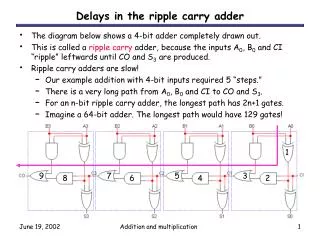
International Research Research and Development (IJTSRD) International Open Access Journal Optimized Carry Speculative Adder Pavan Kumar, M. Lalitha Bhavani, Y. Himanth istant Professor, Department of ECE, Technology & Engineering, Tadepalligudem, India International Journal of Trend in Scientific Scientific (IJTSRD) International Open Access Journal ISSN No: 2456 ISSN No: 2456 - 6470 | www.ijtsrd.com | Volume 6470 | www.ijtsrd.com | Volume - 2 | Issue – 3 Optimized Carry Speculative Adder B. V. Pavan Kumar, M. Assis SASI Institute of Technology & Engineering, Tadepalligudem, India Technology & Engineering, Tadepalligudem, India ABSTRACT Arithmetic logic units and digital signal processors widely uses adders. It is the most complicated arithmetic circuits in digital electronics. The existing adders suffer from critical path delay, area overhead and power consumption. Speculative adders are designed with variable latency that combines speculation technique methodology to attain high performance in terms of low area overhead over the existing adders. In speculative adders the sum and carry generation part is separated to reduce the area overhead. Carry Speculative Adder (CSPA) uses carry predictor circuit to reduce power consumption and to reduce the computational time and it uses error recognition and error correction circuit to find the fault occurred in the partial sum generator and to recover it to get accurate results. Keywords: Arithmetic logic units(ALUs), Digital Signal Processors(DSPs), Carry Speculative Adder (CSPA) I. INTRODUCTION Arithmetic logic units and digital signal processors widely uses adders. It is the most complicated arithmetic circuits in digital electronics. The existing r from critical path delay, area overhead and power consumption. Speculative adders are Any changes made to one parameter may affect any other two parameters. Approximation can increase performance or reduces power consumption with a Any changes made to one parameter may affect any other two parameters. Approximation can increase performance or reduces power consumption with a simplified or inaccurate circuit by sacr simplified or inaccurate circuit by sacrificing output. In this, Carry Speculative Adder Using Modified Carry Generators is proposed which generates sub logarithmic delay with less area and delay and also implementing with variable latency, which gives same results similar former adder and can be used in DSP In this, Carry Speculative Adder Using Modified Carry Generators is proposed which generates sub logarithmic delay with less area and delay and also implementing with variable latency, which gives same results similar former adder and can b Applications. II. METHODOLOGY latency that combines speculation methodology to attain high performance in terms of technique along along with with correction correction existing adders. In speculative adders the sum and carry generation part is separated to reduce the area overhead. Carry Speculative Adder (CSPA) uses carry predictor circuit to reduce power consumption and to reduce the r recognition and Carry Speculative Adder (CSPA) is used to reduce the critical path delay of the circuit. It is based on carry speculation. The block diagram of the carry speculative adder (CSPA) is shown in figure 2.1 speculative adder (CSPA) is shown in figure 2.1 Carry Speculative Adder (CSPA) is used to reduce the critical path delay of the circuit. It is based on carry speculation. The block diagram of the carry error correction circuit to find the fault occurred in the partial sum generator and to recover it to get accurate Arithmetic logic units(ALUs), Digital Carry Speculative Adder rry Speculative Adder is divided into several small blocks adders and Carry Predictor Circuits that are operated independently. Except for the leftmost block adder, the size of each block adder size is x. Number of block adders is represented as The n-bit Carry Speculative Adder is divided into several small blocks adders and Carry Predictor Circuits that are operated independently. Except for the leftmost block adder, the size of each block adder size is x. Number of block adders is represented as ‘m’. Therefore, There are ‘m’ independent block adders and ‘(m − 1)’carry predictor circuits in a Carry Speculative Adder. The value of m is given as by equation 2.1. m= (n/x) ……………….1.1 Circuit delay plays a key role in any system particularly in Adders. Addition is a crucial arithmetic operation because it usually involves a carry ripple which propagates from each bit to its next higher bit position. This results in a substantial circuit Their throughput affects the overall performance of the system. Traditional n-bit adders provide accurate results, but the lower bound of their critical path delay is Ω (log n) i.e.,logarithmic delay that is long delay and requires large power consumption. There is always a trade-off between Area, Power and Delay. off between Area, Power and Delay. Circuit delay plays a key role in any system particularly in Adders. Addition is a crucial arithmetic operation because it usually involves a carry ripple which propagates from each bit to its next higher bit position. This results in a substantial circuit delay. Their throughput affects the overall performance of bit adders provide accurate results, but the lower bound of their critical path delay is Ω (log n) i.e.,logarithmic delay that is long delay efore, There are ‘m’ independent block adders − 1)’carry predictor circuits in a Carry Speculative Adder. The value of m is given as by m= (n/x) ……………….1.1 umption. There is @ IJTSRD | Available Online @ www.ijtsrd.com @ IJTSRD | Available Online @ www.ijtsrd.com | Volume – 2 | Issue – 3 | Mar-Apr 2018 Apr 2018 Page: 1128
International Journal of Trend in Scientific Research and Development (IJTSRD) ISSN: 2456-6470 Table 1: Truth Table of Carry out Signal in Traditional Full Adder CIN A B COUT 0 0 0 0 0 0 1 0 0 1 0 0 0 1 1 1 1 0 0 0 1 0 1 1 1 1 0 1 1 1 1 1 Table 2: Truth Table of Modified Carry Generators When Cin=0 When Cin=1 Fig 2.1: Block diagram of carry speculative adder A B COUT A B COUT III. DETAILED DESIGN 0 0 0 0 0 0 Modified Carry Generators: 0 0 0 0 1 1 1 0 0 1 0 1 In Carry Speculative Adder, the Block Adder is implemented with Modified Full Adder. It separates Carry Generator and Sum Generator to produce carry output and sum out outputs with an extra logic gate which leads to increase in power consumption and area increase. To reduce the area and improve performance of adder, these carry generators in block adder of Carry Speculative Adder are replaced by using two separate carry generators for inputs Cin=1 and Cin=0 respectively. In Traditional Full Adder, the carry out signal equation is given by equation 3.1. Using logic complexity reduction, the Carryout signal equation is simplified to equation 3.2 and equation 3.3 as follows. The truth table of carry generator and modified carry generators is shown below. COUT= A.B+B.C+C.A ….. 3.1 When Cin=0, COUT= A.B ….. 3.2 When Cin=1, COUT= A+B ….. 3.3 1 1 1 1 1 1 The block diagrams of carry generators are shown in figure 3.1 and figure 3.2. When carry in input of block adder is logic one, the carry generator is replaced with logic OR gate and when carry in input of block adder is logic zero, the carry generator is replaced with logic AND gate respectively. Thus in block adders, instead of two carry generators, two types of modified carry generators are used to implement the block adder of Carry Speculative Adder which provides one gate delay with reduced area. These carry generators generate Carry’s simultaneously without using Cin bit. Figure 3.1: Block Diagram of Modified Carry Generator for Cin=1 @ IJTSRD | Available Online @ www.ijtsrd.com | Volume – 2 | Issue – 3 | Mar-Apr 2018 Page: 1129
International Journal of Trend in Scientific Research and Development (IJTSRD) ISSN: 2456-6470 Adder using Modified Carry Generators. When an error is occurred, the input registers in the Variable Latency Carry Speculative Adder using Modified Carry Generators (VLCSPAM) are disabled and no new input is latched in the circuit. Hence to get continuous data in the circuit, a data latching circuit which consists of Xor gate is replace in place of not gate. In the latching circuit, an exclusive or operation is performed between Error signal and complement of Error signal. The output of data latching circuit valid enables to latch new data into input registers after the old data is recovered. A.RESULTS RTL schematic of existing technique: Figure 3.2: Block Diagram of Modified Carry Generator for Cin=0 IV. VARIABLE SPECULATIVE MODIFIED CARRY GENERATORS In Variable Latency Carry Speculative Adder using Modified Carry Generators (VLCSPAM), Carry Speculative Adder using Modified Carry Generators is added with Error detection circuit, Error recovery circuit, Data latching circuit and multi-bit multiplexor as shown in figure 4.1.When an input pattern is arrived, Variable Latency Carry Speculative Adders using Modified Carry Generators gives the result of the Carry Speculative Adder using Modified Carry Generators (i.e., SUM*) in a one cycle. The error detection circuit determines whether an error has occurred or not and also indicates which block adder produces the incorrect partial sum and correct partial sum. LATENCY ADDER CARRY USING Simulation results of Carry Speculative Adder: Here, the size of the Carry Speculative Adder is 32 bit; length of each block adder is 12 bit and number of block adders is equal to 3. Here the signal VCC is set at high and GND is set at low. The input A is given as “0000 0000 0000 0001 1110 0110 0110 1011” which equal to “255595” in decimal and input B is given as “0000 000 0010 0011 0101 1000 1110 1011” which equal to “2316523” in decimal. The sum of the two numbers in normal addition process is “2572118”. Figure 4.1: Variable Latency Carry Speculative Adder using Modified Carry Generators The error recovery circuit recovers the results when an error occurs based on the ERR_block in the next clock cycle. The results from error recovery circuit and Carry Speculative Adder using Modified Carry Generators are given to multi-bit multiplexor and the error is used as multiplexor select signal to select one of the sum results. When the ER signal is “1”, the multiplexor selects recovers signal from error recovery circuit. When the ER signal is “0”, the multiplexor selects results from Carry Speculative Simulation Results for Carry Speculative Adder using Modified Carry Generators: Figure below shows the simulation results of Carry Speculative Adder using Modified Carry Generators. Here, the size of the Carry Speculative Adder using @ IJTSRD | Available Online @ www.ijtsrd.com | Volume – 2 | Issue – 3 | Mar-Apr 2018 Page: 1130
International Journal of Trend in Scientific Research and Development (IJTSRD) ISSN: 2456-6470 Modified Carry Generators is 32 bit; length of each block adder is 12 bit and number of block adders is equal to 3. Here the signal VCC is set at high and GND is set at low. The input A is given as “0000 0000 0000 0001 1110 0110 0110 1011” which equal to “255595” in decimal and input B is given as “0000 000 0010 0011 0101 1000 1110 1011” which equal to “2316523” in decimal. The sum of the two numbers in normal addition process is “2572118”. Test Conference Exhibition (DATE), Mar. 2012, pp. 1257- 1262. 4.Y.-H. Su, D.-C. Wang, S.-c. Chang, and M.-S. Malgorzata, "Performance optimization using variable-latency design style," IEEE Transaction Very Large Scale Integration (VLSI) Systems, vol. 19, no. 10, pp. 1874-1883, Oct. 2011. 5.D. Baneres, 1. Cortadella, and M. Kishinevsky, "Variable-latency design by function speculation," in Proceedings, Design Co'!ference Exhibition (DATE), Apr. 2009, pp. 1704-1709. Automation Test 6.D. Shin and S. K. Gupta, "Approximate logic synthesis for error tolerant applications," in Proceedings, Design Automation Test Cof!ference Exhibition. (DATE), Mar. 2010, pp. 957-960. 7.A.K. Verma, P. Brisk, and P. lenne, "Variable latency speculative addition: A new paradigm forarithmetic circuit design," in Proceedings, Design Automation Test Cof!ference Exhibition (DATE), Mar. 2008, pp. 1250-1255. CONCLUSION: Carry Speculative Adder using Modified Carry Generators uses separate carry generators circuits to generate carry signals with less number of gates compared to traditional full adder. Carry Speculative Adder using Modified Carry Generators improves the performance of the adder and reduces the area producing accurate results. Carry Speculative Adder using Modified Carry Generators is also implemented with variable latency design to produce accurate results. 8.A. B. Kahng and S. Kang, "Accuracy-configurable adder for approximate arithmetic designs,"I in Proceedings, Design Automation Conference. (DAC), 2012, pp. 820-825. 9.Y. Liu, Y. Sun, Y. Zhu, and H. Yang, "Design methodology of variable speculation," in Proc. Symposium Qual Electron. Design (ISQED), Mar. 2010, pp. 824-830. multistagefunction 11th International 10.M. Olivieri, "Design of synchronous and asynchronous variable-latency multipliers," IEEE Transaction Very Large Scale Integration (VLSf) Systems., vol. 9, no. 2, pp. 365-376, Apr. 2001. REFERENCES pipelined 1.Latency Raghunathan, V. Gupta and K. Roy, "Low-power digital signal processing using approximate adders, " IEEE Transaction Computer- Aided Design Integration Circuits Systems., vol. 32, no. I, pp. 124-137, Jan. 2013. adders with D. Mohapatra, A. 11.Y. Chen, H. Li, J. Li, and c.-K. Koh, "Variable- latency adder (VLadder): New arithmetic circuit design practice to Proceedings Internationl. Symposium Low Power Electronic Design (ISLPED), Aug. 2007, pp. 195- 200. overcome NBTI," in 2.N. Zhu, K. S. Yeo, W. L. Goh, and Z. H. Kong, "Design of low-power high-speed truncation- error-tolerantadder and its application in digital signal processing," IEEE Transaction Very Large Scale Integration (VLSf) Syst., vol. 18, no. 8, pp. 1225-1229, Aug. 2010. 3.P. Varman, K. Du and K. Mohanram, "High performance reliable variable latency carry select addition," in Proceedings, Design Automation @ IJTSRD | Available Online @ www.ijtsrd.com | Volume – 2 | Issue – 3 | Mar-Apr 2018 Page: 1131