Download
1 / 4
40 likes | 53 Vues
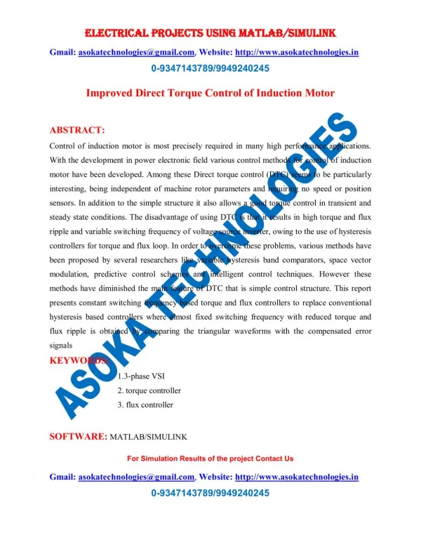
Escalator is useful and act in the important part to carry passengers to the targeted floors of building. Every escalator must be driven by its own motor and this motor speed must be controled. To drive escalator with a constant speed, direct torque control technique is used to drive three phase squirrel cage induction motor. In this paper, the development of speed control system for three phase squirrel cage induction motor using a direct torque control method is presented and simulation for proposed system is done with the help of MATLAB SIMULINK. Soe Sandar Aung | Thet Naing Htun "Speed Control System of Induction Motor by using Direct Torque Control Method used in Escalator" Published in International Journal of Trend in Scientific Research and Development (ijtsrd), ISSN: 2456-6470, Volume-3 | Issue-5 , August 2019, URL: https://www.ijtsrd.com/papers/ijtsrd27903.pdf Paper URL: https://www.ijtsrd.com/engineering/electrical-engineering/27903/speed-control-system-of-induction-motor-by-using-direct-torque-control-method-used-in-escalator/soe-sandar-aung<br>

E N D
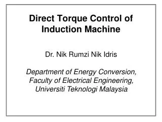
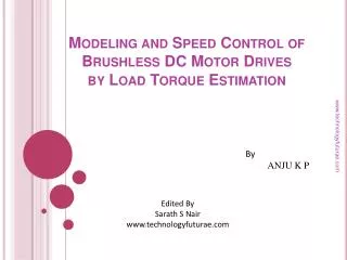
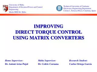
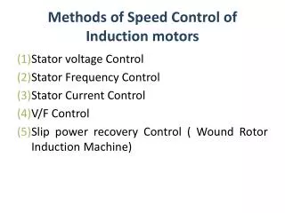
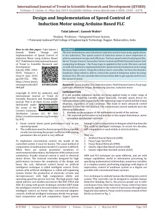
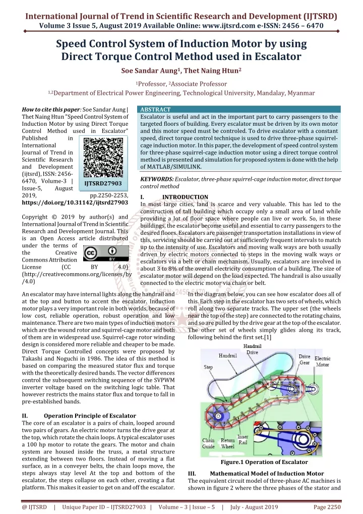
International Journal of Trend in Scientific Research and Development (IJTSRD) Volume 3 Issue 5, August 2019 Available Online: www.ijtsrd.com e-ISSN: 2456 – 6470 Speed Control System of Induction Motor by using Direct Torque Control Method used in Escalator Soe Sandar Aung1, Thet Naing Htun2 1Professor, 2Associate Professor 1,2Department of Electrical Power Engineering, Technological University, Mandalay, Myanmar How to cite this paper: Soe Sandar Aung | Thet Naing Htun "Speed Control System of Induction Motor by using Direct Torque Control Method used in Escalator" Published in International Journal of Trend in Scientific Research and Development (ijtsrd), ISSN: 2456- 6470, Volume-3 | Issue-5, August 2019, https://doi.org/10.31142/ijtsrd27903 Copyright © 2019 by author(s) and International Journal of Trend in Scientific Research and Development Journal. This is an Open Access article distributed under the terms of the Creative Commons Attribution License (CC (http://creativecommons.org/licenses/by /4.0) An escalator may have internal lights along the handrail and at the top and button to accent the escalator. Induction motor plays a very important role in both worlds, because of low cost, reliable operation, robust operation and low maintenance. There are two main types of induction motors which are the wound rotor and squirrel-cage motor and both of them are in widespread use. Squirrel-cage rotor winding design is considered more reliable and cheaper to be made. Direct Torque Controlled concepts were proposed by Takashi and Noguchi in 1986. The idea of this method is based on comparing the measured stator flux and torque with the theoretically desired bands. The vector differences control the subsequent switching sequence of the SVPWM inverter voltage based on the switching logic table. That however restricts the mains stator flux and torque to fall in pre-established bands. II. Operation Principle of Escalator The core of an escalator is a pairs of chain, looped around two pairs of gears. An electric motor turns the drive gear at the top, which rotate the chain loops. A typical escalator uses a 100 hp motor to rotate the gears. The motor and chain system are housed inside the truss, a metal structure extending between two floors. Instead of moving a flat surface, as in a conveyer belts, the chain loops move, the steps always stay level At the top and bottom of the escalator, the steps collapse on each other, creating a flat platform. This makes it easier to get on and off the escalator. ABSTRACT Escalator is useful and act in the important part to carry passengers to the targeted floors of building. Every escalator must be driven by its own motor and this motor speed must be controled. To drive escalator with a constant speed, direct torque control technique is used to drive three-phase squirrel- cage induction motor. In this paper, the development of speed control system for three-phase squirrel-cage induction motor using a direct torque control method is presented and simulation for proposed system is done with the help ofMATLAB/SIMULINK. KEYWORDS: Escalator, three-phase squirrel-cage induction motor, direct torque control method I. INTRODUCTION In most large cities, land is scarce and very valuable. This has led to the construction of tall building which occupy only a small area of land while providing a lot of floor space where people can live or work. So, in these buildings, the escalator become useful and essential to carry passengers to the desired floors. Escalators are passenger transportation installations in view of this, servicing should be carried out at sufficiently frequent intervals to match up to the intensity of use. Escalators and moving walk ways are both usually driven by electric motors connected to steps in the moving walk ways or escalators via a belt or chain mechanism. Usually, escalators are involved in about 3 to 8% of the overall electricity consumption of a building. The size of escalator motor will depend on the load expected. The handrail is also usually connected to the electric motor via chain or belt. In the diagram below, you can see how escalator does all of this. Each step in the escalator has two sets of wheels, which roll along two separate tracks. The upper set (the wheels near the top of the step) are connected to the rotating chains, and so are pulled by the drive gear at the top of the escalator. The other set of wheels simply glides along its track, following behind the first set.[1] IJTSRD27903 pp.2250-2253, BY 4.0) Figure.1 Operation of Escalator Mathematical Model of Induction Motor The equivalent circuit model of three-phase AC machines is shown in figure 2 where the three phases of the stator and III. @ IJTSRD | Unique Paper ID – IJTSRD27903 | Volume – 3 | Issue – 5 | July - August 2019 Page 2250
International Journal of Trend in Scientific Research and Development (IJTSRD) @ www.ijtsrd.com eISSN: 2456-6470 the rotor are both modeled by inductive components and appropriate AC voltage sources. The stator three phase input voltages, from the artificial V mains, are given in Equation 1 to Equation 3 as well as the induced rotor three phase voltages which are given in Equation 4 to Equation 6.[2] Where P is the number of pole and Te is the electromagnetic torque TL is load torque, J is the inertia of the rotor and connected load B is the friction. IV. Propose Control System of Induction Motor Using Direct Torque Control Scheme The conventional DTC scheme is a closed loop control scheme, the important elements of the control structure being: the power supply circuit, a three phase voltage source inverter, the induction motor, the speed controller to generate the torque command and the DTC controller. The DTC controller again consists of torque and flux estimation block, two hysteresis controllers and sector selection block, the output of the DTC controller is the gating pulses for the inverter. The DTC scheme does not require coordinate transformation as all the control procedures are carried out in stationary frame of reference. So this scheme does not suffer from parameter variations to the extent that other control techniques do. Also there is no feedback current control loop due to which the control actions do not suffer from the delays inherent in the current controllers, no pulse width modulator, no PI controllers and no rotor speed or position sensor. So it is a sensorless control technique, which operates the motor without requiring a shaft mounted mechanical sensor. Here on-line torque and flux estimators are used for closing the loop. Here the torque and stator flux are controlled directly by using hysteresis comparators.[3] The basic principle of DTC is to directly select stator voltage vectors according to the torque and flux errors which are the differences between the references of torque and stator flux linkage and their actual values. The governing equation for torque for this scheme is due to the interaction of stator and rotor fields. Torque and stator flux linkage are computed from measured motor terminal quantities i.e. stator voltages and current. An optimal voltage vector for the switching of VSI is selected among the six nonzero voltage vectors and two zero voltage vectors by the hysteresis control of stator flux and torque. This method of control implies a comparative control of the torque and stator flux. It is more used in controlling induction machine because it is considered a simple and robust method. The stator current and voltage are indirectly controlled hence no current feedback loops are required. Nearly sinusoidal stator fluxes and stator currents enable high dynamic performances even at standstill. The generic DTC scheme for a Voltage source PWM inverter-fed IM drive is shown in figure 3.[4] Figure.2 Equivalent Circuit Model of Three-phase AC Machine The stator of induction motor consists of three phase balanced distributed winding with each phase separated from the other two winding by 120 degrees in space. When current flows through these windings, three phase rotating magnetic field is produced. The dynamic behavior of the induction motor is taken into account in an adjustable speed drive system using a power electronic converter. This machine constitutes an element with in a feedback loop. Study of dynamic performance of machine is complex due to the coupling effect of the stator and rotor windings; also the coupling coefficient varies with the rotor position. So a set of differential equations with time varying coefficients described the machine model. The electromagnetic torque of the machine can be written as: Figure.3 Block Diagram of Space Vector PWM DTC Control @ IJTSRD | Unique Paper ID – IJTSRD27903 | Volume – 3 | Issue – 5 | July - August 2019 Page 2251
International Journal of Trend in Scientific Research and Development (IJTSRD) @ www.ijtsrd.com eISSN: 2456-6470 V. Modeling of Speed Control System for Squirrel- cage Induction Motor Using Direct Torque Control For the speed control system for squirrel-cage induction motor, the modeling and simulation is carried out with MATLAB/SIMULINK software. For the modeling 3.7kW, 400V squirrel-cage induction motor is used and parameters are shown in table 1. Table.1 Parameters of BLDC motor Rated Power, kW Rated Voltage, V Rated Torque, Nm Rated Speed, rpm Connection of stator winding Type of rotor Frequency, Hz No. of pole The simulink model for the speed control system for squirrel-cage induction motor is shown in figure 4. . The motor is fed from an IGBT PWM inverter. In this drive, the speed is set at 750 rpm and the flux reference is maintained at 0.8. At 0.6 sec the load torque change from no-load to 3.48 Nm for one person load, at 1.8 sec the load torque change from 3.48 Nm to 17.4 Nm for five persons, at 3 sec the load change from 17.4 to 41.76 Nm for twelve persons, at 4.2 sec the torque change from 41.76 Nm to 3.48 Nm for two persons and at 5.4 sec the load torque change from 3.48 Nm to 0. Figure 6 shows the resultant speed response of the machine at different load torque. In figure 6, the speed reaching to the desired speed at 0.3 sec and at when escalator is loaded 3.48 Nm (one person), the speed decreases to the 700 rpm and return to the desired speed in 0.2 sec. When the load torque is changed from 3.8 Nm to 17.4 Nm for five persons, the speed decreases to the 650 rpm and return to the desired speed in 0.3 sec. When the load torque is changed from 17.4 Nm to 41.76 Nm for twelve persons, the speed decreases till 410 rpm and return to the desired speed in 0.4 sec. When the load torque is changed from 41.76 Nm to 3.48 Nm for one person, the speed increases till 1300 rpm and return to the desired speed in 0.4 sec. When the load torque is changed from 3.8 Nm to 0 for no load, the speed increases to the 800 rpm and return to the desired speed in 0.2 sec. 3.7 400 41.76 1450 Star Cage rotor 50 4 Figure6. Speed Response of Direct Torque Control An increase and decrease of the load on the shaft of the motor developing increase and decrease of electromagnetic torque as indicating in figure.7. The torque in, which is smoothly following the load torque and it reaches the desired torque slower. As shown in figure 7, the actual torque follows reference torque very fast when reference load torque changes. Figure4. Simulink model for the speed control system for squirrel-cage induction motor VI. Figure 5 shows stator currents of induction machine with sudden change in load torque of escalator. In this case it is seen that, when the load on the motor is increased the motor currents are increased and when the load on the motor is decreased the motor currents are decreased. At maximum load torque 41.76 Nm for twelve persons, the current is reaching to the 22 A. Result Figure7. Electromagnetic Torque of Direct Torque Control VII. This paper presents the speed control of squirrel-cage induction motor using Direct Torque Control method with Space Vector PWM was MATLAB/SIMULINK. In Direct Torque Control system, a closed loop speed control technique is used for the squirrel- cage induction motor. In DTC scheme, the torque and current Conclusion implemented using Figure5. Three-phase Currents Response of Direct Torque Control @ IJTSRD | Unique Paper ID – IJTSRD27903 | Volume – 3 | Issue – 5 | July - August 2019 Page 2252
International Journal of Trend in Scientific Research and Development (IJTSRD) @ www.ijtsrd.com eISSN: 2456-6470 ripple are minimized by employing space vector modulation technique and the torque response is fast and smooth reach to the desired load torque. References [1].Taninecz, G.: Schindler Escalator Corp, Industry Week, (1996) [5].Sprecher, S. A. G. R. A.: Application Basics of Operation ofThree-phase Induction Motors, (1996). [6].Ashfaq, A.: Power Electronics for Technology, Hall International, Inc., International Edition, (1999). [7].Anett, F.A.: Electric Elevators, Second Edition, Printed by McGraw Hill Book Company, Inc (1935). [2].Ong, C. M.: Dynamic simulation of electric machinery: using MATLAB/SIMULINK, vol. 5, Prentice Hall PTR Upper Saddle River, NJ, (1998). [8].Buja, G.S. and Marian, P. K.: Direct Torque control of PWM Inverter-Fed AC Motor – A Survey, IEEE Transactions on Industrial Electronics, Vol. 1, No. 4, pp. 344-350, (2004). [3].Chee-Mun, O.: Dynamic Simulation of ElectricMachinery using Matlab/Simulink, A Simon and Schuster Company, Upper Saddle River, New Jersey, (1997). [9].Wang, X., Yang, Y.andLiu, W.: Simulation of vector controlled adjustable speed System of induction motor based on Simulink, pp. 2563-2566,(2011). [4].Nash, J. N.: Direct torque control, induction motor vector control without an encoder, Industry Applications, IEEE Transactions on, vol. 33, pp. 333-341, (1997). @ IJTSRD | Unique Paper ID – IJTSRD27903 | Volume – 3 | Issue – 5 | July - August 2019 Page 2253