Download
1 / 1
10 likes | 101 Vues
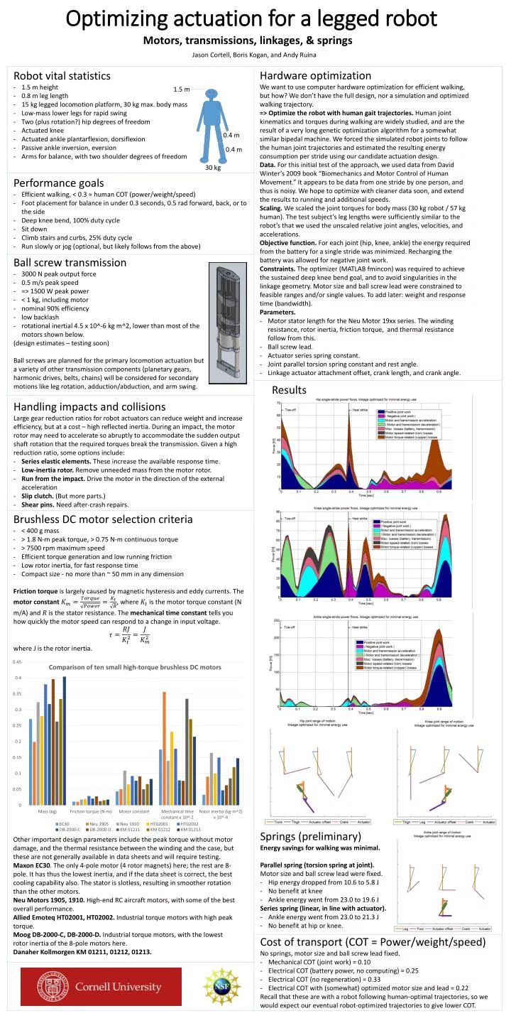
Jason Cortell, Boris Kogan , and Andy Ruina. Hardware optimization We want to use computer hardware optimization for efficient walking, but how? We don’t have the full design, nor a simulation and optimized walking trajectory.

E N D
Jason Cortell, Boris Kogan, and Andy Ruina • Hardware optimization • We want to use computer hardware optimization for efficient walking, but how? We don’t have the full design, nor a simulation and optimized walking trajectory. • => Optimize the robot with human gait trajectories. Human joint kinematics and torques during walking are widely studied, and are the result of a very long genetic optimization algorithm for a somewhat similar bipedal machine. We forced the simulated robot joints to follow the human joint trajectories and estimated the resulting energy consumption per stride using our candidate actuation design. • Data. For this initial test of the approach, we used data from David Winter’s 2009 book “Biomechanics and Motor Control of Human Movement.” It appears to be data from one stride by one person, and thus is noisy. We hope to optimize with cleaner data soon, and extend the results to running and additional speeds. • Scaling. We scaled the joint torques for body mass (30 kg robot / 57 kg human). The test subject’s leg lengths were sufficiently similar to the robot’s that we used the unscaled relative joint angles, velocities, and accelerations. • Objective function. For each joint (hip, knee, ankle) the energy required from the battery for a single stride was minimized. Recharging the battery was allowed for negative joint work. • Constraints. The optimizer (MATLAB fmincon) was required to achieve the sustained deep knee bend goal, and to avoid singularities in the linkage geometry. Motor size and ball screw lead were constrained to feasible ranges and/or single values. To add later: weight and response time (bandwidth). • Parameters. • Motor stator length for the Neu Motor 19xx series. The winding resistance, rotor inertia, friction torque, and thermal resistance follow from this. • Ball screw lead. • Actuator series spring constant. • Joint parallel torsion spring constant and rest angle. • Linkage actuator attachment offset, crank length, and crank angle. • Robot vital statistics • 1.5 m height • 0.8 m leg length • 15 kg legged locomotion platform, 30 kg max. body mass • Low-mass lower legs for rapid swing • Two (plus rotation?) hip degrees of freedom • Actuated knee • Actuated ankle plantarflexion, dorsiflexion • Passive ankle inversion, eversion • Arms for balance, with two shoulder degrees of freedom 1.5 m 0.4 m 0.4 m 30 kg Optimizing actuation for a legged robot • Performance goals • Efficient walking, < 0.3 ≈ human COT (power/weight/speed) • Foot placement for balance in under 0.3 seconds, 0.5 rad forward, back, or to the side • Deep knee bend, 100% duty cycle • Sit down • Climb stairs and curbs, 25% duty cycle • Run slowly or jog (optional, but likely follows from the above) • Ball screw transmission • 3000 N peak output force • 0.5 m/s peak speed • => 1500 W peak power • < 1 kg, including motor • nominal 90% efficiency • low backlash • rotational inertial 4.5 x 10^-6 kg m^2, lower than most of the motors shown below. • (design estimates – testing soon) • Ball screws are planned for the primary locomotion actuation but a variety of other transmission components (planetary gears, harmonic drives, belts, chains) will be considered for secondary motions like leg rotation, adduction/abduction, and arm swing. Results • Handling impacts and collisions • Large gear reduction ratios for robot actuators can reduce weight and increase efficiency, but at a cost – high reflected inertia. During an impact, the motor rotor may need to accelerate so abruptly to accommodate the sudden output shaft rotation that the required torques break the transmission. Given a high reduction ratio, some options include: • Series elastic elements. These increase the available response time. • Low-inertia rotor. Remove unneeded mass from the motor rotor. • Run from the impact. Drive the motor in the direction of the external acceleration • Slip clutch. (But more parts.) • Shear pins. Needafter-crash repairs. • Brushless DC motor selection criteria • < 400 g mass • > 1.8 N-m peak torque, > 0.75 N-m continuous torque • > 7500 rpm maximum speed • Efficient torque generation and low running friction • Low rotor inertia, for fast response time • Compact size - no more than ~ 50 mm in any dimension • Friction torque is largely caused by magnetic hysteresis and eddy currents. The motor constant, where is the motor torque constant (N m/A) and is the stator resistance. The mechanical time constant tells you how quickly the motor speed can respond to a change in input voltage. • where J is the rotor inertia. Motors, transmissions, linkages, & springs • Springs (preliminary) • Energy savings for walking was minimal. • Parallel spring (torsion spring at joint). Motor size and ball screw lead were fixed. • Hip energy dropped from 10.6 to 5.8 J • No benefit at knee • Ankle energy went from 23.0 to 19.6 J • Series spring (linear, in line with actuator). • Ankle energy went from 23.0 to 21.3 J • No benefit at hip or knee. Other important design parameters include the peak torque without motor damage, and the thermal resistance between the winding and the case, but these are not generally available in data sheets and will require testing. Maxon EC30. The only 4-pole motor (4 rotor magnets) here; the rest are 8-pole. It has thus the lowest inertia, and if the data sheet is correct, the best cooling capability also. The stator is slotless, resulting in smoother rotation than the other motors. Neu Motors 1905, 1910. High-end RC aircraft motors, with some of the best overall performance. Allied Emoteq HT02001, HT02002. Industrial torque motors with high peak torque. Moog DB-2000-C, DB-2000-D. Industrial torque motors, with the lowest rotor inertia of the 8-pole motors here. Danaher Kollmorgen KM 01211, 01212, 01213. • Cost of transport (COT = Power/weight/speed) • No springs, motor size and ball screw lead fixed. • Mechanical COT (joint work) = 0.10 • Electrical COT (battery power, no computing) = 0.25 • Electrical COT (no regeneration) = 0.33 • Electrical COT with (somewhat) optimized motor size and lead = 0.22 • Recall that these are with a robot following human-optimal trajectories, so we would expect our eventual robot-optimized trajectories to give lower COT.