Download
1 / 18
180 likes | 328 Vues
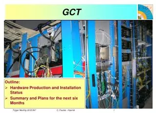
CMS GCT Hardware - Wheel Card. 11/8/06. GCT Block Diagram. Leaf Card. Concentrator card. Wheel Card. Wheel Card Functions. Carries 3 leaf cards (double PMC) Compresses (sorts) Jet data Calculates Et and Jet count Single ended electrical interface (DDR 40MHz) Extra PMC supported

E N D
CMS GCT Hardware - Wheel Card 11/8/06
GCT Block Diagram Leaf Card Concentrator card Wheel Card
Wheel Card Functions • Carries 3 leaf cards (double PMC) • Compresses (sorts) Jet data • Calculates Et and Jet count • Single ended electrical interface (DDR 40MHz) • Extra PMC supported • Not used for initial functionality • Interfaces to concentrator board • High speed cable interface • LVDS electrical interface • DDR 40Mhz required, but could support higher • 9U VME form factor • Power only, no VME interface • ECAL backplane
Hardware Connectivity • Accepts parallel data from leafs on 3 DPMC sites • 278 signals on each site (total 834) • 186 signals/site to Jet FPGA, 92/site to Energy FPGA • Single ended • Extra PMC site for future use • 165 signals • Outputs parallel data • Jet data processed further on concentrator card • Count • 4 highest Et • Electrical interface • 240 differential pairs provided
Wheel Card Connections Finished Jet data Energy Sum Data J1 Leaf (x3) J 13 J 14 Diff Buffers J 11 J 12 J2 Jet FPGA Energy FPGA J 23 J 24 J3 Diff Buffers J 21 J 22
Implementation • Data Handling • Eta 0 data duplicated to eliminate unfinished jets • Sent to leaf cards on each half barrel • All jets finished on leaf cards • Wheel and concentrator sort • Processing • Two Xilinx Virtex4 FPGAs • XC4VLX100FF1513 • I/O (as opposed to logic) intensive design • Advanced Virtex4 I/O features reduce risk • Better double data rate support • Improved Differential support • One for Jet sorting, one for Et and Jet count • Jet FPGA pin limited • Requires single ended output to meet signal count • External differential buffers drive data to concentrator
Electrical Interfaces • LVDS signaling • Jet FPGA drives indirectly • 40MHz DDR required, but can support faster • TI LVDS buffers rated at 200MHz, likely limited to 100MHz in this application • Single ended signals from FPGA not length matched, driving 2.5V LVCMOS into 3.3V inputs • Energy FPGA drives directly • Direct V4/V4 connection provides maximum flexibility and speed • Samtec QTS/H differential connectors • High density and speed, Rated for multi GHz operation • Commercial cable assemblies • DDR used for all single ended I/O • FPGA intercommunication at 40MHz • Short runs allow faster operation • Communication with Leaf cards at 40MHz • PMC connectors limit speed here • Leaf cards utilize 2.5V LVCMOS with DCI (nominally 50 ohms at this point) • Single ended outputs from FPGAs utilize DCI drivers • Allow controlled impedance drive • Nominally 50 ohms at this point
Clock Tree Differential clocks Octal Fanout A FPGA control PMC sites (4) 40Mhz FPGAs (4) QPLL 4x4 Crosspoint 80MHz Octal Fanout B 40MHz from Concentrator PMC sites (4) 80MHz from Concentrator FPGAs (4) Output connector Single ended clocks 1:10 fanout 40 MHz Osc PMC sites (7) FPGAs (2)
Clock Distribution JET/ENERGY FPGA Top Die (bank 3) Differential Fanout A Clock Single ended Fanout Clock PMC (x4) Differential Fanout A Clock Differential Fanout B Clock Single ended Fanout Clock JET/ENERGY FPGA Bottom Die (bank 4) Differential Fanout A Clock Differential Fanout B Clock Single ended Fanout Clock Differential Fanout B Clock The clock distribution system insures all FPGAs have access to multiple clock sources. The single ended clock is not switched, and is intended to be used for diff clock control and state of health functions. The QPLL may glitch if not locked – DCM performance may be adversely effected, their use may need to be avoided in the firmware design.
Power supplies • 10A, 1.2V switcher for each V4 VccInt • Devices can be run near thermal limit • Estimated load less than 1/2 this figure at 40MHz • Two 10A, 2.5V switchers for I/O • Leaf cards may be jumpered to provide own VIO • Wheel will only need to drive own FPGAs • 10A, 3.3V switcher for each DPMC site • Board design allows for substitution of 5A Linear • Would be preferable since optical receivers are powered directly • Questionable margin requires switcher site be provided • All Switchers powered from 5V • Not used for other logic • Separate linear supply for QPLL and some clock distribution • 2.5V
FPGA Configuration • JTAG • CPLD JTAG switch controls 8 independent chains • Single JTAG header switched to multiple chains • Individual chains can be daisy chained together or bypassed • JTAG interface vial front paned connector or concentrator • Configured by front panel switches • 3.3V external interface • CPLD reprogrammable by dedicated JTAG connector only • Individual JTAG chains (6 of 8 used) • 3 Leaf sites • 4 devices, 2 FPGAs and 2 FLASH PROMs each • Extra PMC site (currently unused) • Jet FPGA • 2 devices, FPGA and FLASH PROM • Energy FPGA • 2 Devices, FPGA and FLASH PROM • Default FPGA configuration via Xilinx FLASH PROM • Single platform FLASH XCF32P per device • No dedicated global reset • Define logic reset lines in firmware • Utilize JTAG for device reprogramming
JTAG System Front panel Board header To concentrator CPLD JTAG Samtec differential Connector/cable J T A G Differential buffers S W I T C H E S JTAG SWITCH (CPLD) 6, 2.5V JTAG chains JTAG Mode 2, 3.3V JTAG chains (unused in wheel design) JTAG CPLD is a combinatorial flow-through design A single chain, or multiple chains (daisy chained) are selected via front panel mode switches JTAG source is either front panel header or concentrator, selected by mode switch
Layout Progress • Initial Layout completed • 14 layer board • 7 signal layers • Alternate signal/plane layers • Several issues identified • Slots for leaf card differential links missing • Requires minor PMC site move • Signals cross split plane boundary • One major instance on layer 7 • No length matching implemented • Due to routing congestion • Not an issue at 40MHz • Differential pairs matched to each other • Pairs not matched – possibly creating clocking issues (unlikely at 40MHz) • Need to add mounting holes for differential cable assemblies • Assemblies stiffer than anticipated • Need to verify clearance between differential buffers and connector • POL supplies not ideally located (several inches from FPGAs) • Compromise with signal routing • Netlist verification just starting now • Problems with schematic back annotation using newest Cadence version • Design rolled back to previous version successfully
Plane 7 detail Signals crossing plane boundary
Mitigation • Adding slots for cables requires moving PMC sites • Time consuming, but necessary • Cables in hand, so dimensions well known • Add decoupling capacitors across boundary of split planes • Several (3-4) .1uF caps to AC couple planes at each major crossing point • Also add decouplers near PMC connectors for every power plane layer • Provide return path for image currents in adjacent trace layers • Exact number is TBD, but should be on the order of 20/double PMC • Leaf card is decoupled in a similar fashion • Length matching is not practical at this point • Nets were hand routed, modifications will be time consuming • Matching clock net lengths should be done • At least to the fanout ICs • Mounting holes will not be a problem • Adequate space around connectors • POL supplies can’t be easily moved • Add additional low ESR capacitors near FPGA • >100 uF values as used on leaf card
Complete Board • Use Cadence free physical viewer to view board layer by layer if desired • Version 15.7 (the latest as of 11/8/06) is required to view the Wheel board file
Testing • Stand alone operation possible • Requires special test firmware and software • Extension to current labview based test routines possible • Loaded via local JTAG header • USB interface to PC • USB/PMC loopback designed, but not purchased yet • Based on existing test fixture • Loopback of differential interface • Uses the same cable as in operation • FPGA loopback intrinsic