Download
1 / 10
120 likes | 268 Vues
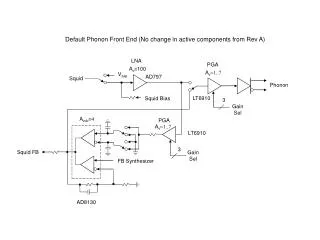
LNA Simulation Tutorial. EE395 Lily Chan Spring 2012 March 22, 2012. Step 1. Open Analog Environment Setup models Setup > model libraries Add paths to models. Step 2. Go to Analyses tab Choose dc analysis Click the box to save DC Operating Point. Step 3. Add variables from schematic

E N D
LNA Simulation Tutorial EE395 Lily Chan Spring 2012 March 22, 2012
Step 1 • Open Analog Environment • Setup models • Setup > model libraries • Add paths to models
Step 2 • Go to Analyses tab • Choose dc analysis • Click the box to save DC Operating Point
Step 3 • Add variables from schematic • Variables > Copy from Cellview • Input variable values
Step 4 • Choose Analyses • Select sp in the Analysis section • Click select in the Ports section • Click on the input and output ports on the schematic • Select Frequency in the Sweep Variable section • Enter the start/stop sweep range • Select Do Noise = yes • Enter your Input and output ports • Click on OK • Click on Netlist and Run (The traffic light button with the green light in the Analog Environment main screen)
Step 5 • After the simulation is done running, click on Results > direct plot > main form • Choose SP > plot type = Z-smith • Then click on S11 and S22 buttons
Step 5 Result • A window with the Smith chart should pop up showing you the S11 and S22 curves
Step 6 • Go back to the Direct plot form from step 5 • Select plot type Rectangular, Modifier = dB20 • Click s11, s22 • These are your input/output impedance matching curves
Step 7 • On the direct plot form, click on S21 • This is your gain
Step 8 • On the direct plot form, choose • Function = NF • Modifier = db10 • Click on Plot • This is your noise figure