Download
1 / 56
640 likes | 1.33k Vues
Today’s Objectives : Students will be able to a) define a couple, and, b) determine the moment of a couple. MOMENT OF A COUPLE. In-Class activities : Check Homework Reading Quiz Applications Moment of a Couple Concept Quiz Group Problem Solving Attention Quiz. READING QUIZ.

E N D
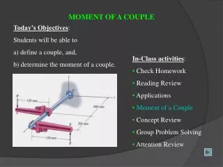
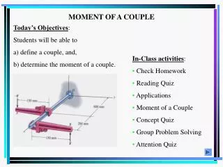
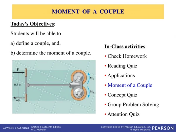
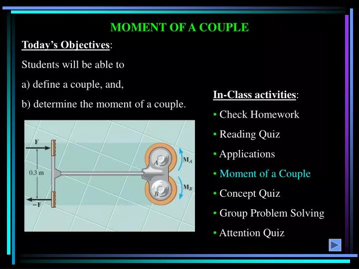
Today’s Objectives: Students will be able to a) define a couple, and, b) determine the moment of a couple. MOMENT OF A COUPLE • In-Class activities: • Check Homework • Reading Quiz • Applications • Moment of a Couple • Concept Quiz • Group Problem Solving • Attention Quiz
READING QUIZ 1. In statics, a couple is defined as __________ separated by a perpendicular distance. A) two forces in the same direction B) two forces of equal magnitude C) two forces of equal magnitude acting in the same direction D) two forces of equal magnitude acting in opposite directions 2. The moment of a couple is called a _________ vector. A) Free B) Spin C) Romantic D) Sliding
A torque or moment of 12 N · m is required to rotate the wheel. Why does one of the two grips of the wheel above require less force to rotate the wheel? APPLICATIONS
When you grip a vehicle’s steering wheel with both hands, a couple moment is applied to the wheel. APPLICATIONS (continued) Would older vehicles without power steering have larger or smaller steering wheels?
A couple is defined as two parallel forces with the same magnitude but opposite in direction separated by a perpendicular distance d. MOMENT OF A COUPLE The moment of a couple is defined as MO = F d (using a scalar analysis) or as MO = r F (using a vector analysis). Here r is any position vector from the line of action of –Fto the line of action ofF.
The net external effect of a couple is that the net force equals zero and the magnitude of the net moment equals F *d. Since the moment of a couple depends only on the distance between the forces, the moment of a couple is a free vector. It can be moved anywhere on the body and have the same external effect on the body. MOMENT OF A COUPLE (continued) Moments due to couples can be added together using the same rules as adding any vectors.
Given: Two couples act on the beam with the geometry shown. Find: The resultant couple Plan: EXAMPLE - SCALAR APPROACH 1) Resolve the forces in x and y directions so they can be treated as couples. 2) Add the two couples to find the resultant couple.
The x and y components of the upper-left 300 lb force are: (4/5)(300 lb) = 240 lb vertically up (3/5)(300 lb) = 180 lb to the left Do both of these components form couples with their matching components of the other 300 force? EXAMPLE - SCALAR APPROACH No! Only the 240 lb components create a couple. Why?
Now resolve the lower 150 lb force: (150 lb) (sin 30°), acting up (150 lb) (cos 30°), acting to the left Do both of these components create a couple with components of the other 150 lb force? The net moment is equal to: + M = – (240 lb)(2 ft) – (150 lb)(cos 30º)(2 ft) = – 480 – 259.8 = -739.8 ft·lb EXAMPLE - SCALAR APPROACH
Given: A 35 N force couple acting on the rod. Find: The couple moment acting on the rod in Cartesian vector notation. Plan: EXAMPLE – VECTOR APPROACH 1) Use M = r F to find the couple moment. 2) Set r =rAB andF = {35 k} N . 3) Calculate the cross product to find M.
rAB = { 0i –(0.25) j + (0.25 tan 30°)k} m rAB = {–0.25 j + 0.1443 k} m F = {0 i+ 0 j+ 35 k} N M =rAB F i j k = N·m 0 –0.25 0.1443 0 0 35 EXAMPLE – VECTOR APPROACH = {(– 8.75 – 0) i – (0 – 0) j – (0 – 0) k} N·m = {– 8.75 i+ 0j +0 k} N·m
1. F1 and F2 form a couple. The moment of the couple is given by ____ . A) r1 F1 B) r2 F1 C) F2 r1 D) r2 F2 CONCEPT QUIZ 2. If three couples act on a body, the overall result is that A) The net force is not equal to 0. B) The net force and net moment are equal to 0. C) The net moment equals 0 but the net force is not necessarily equal to 0. D) The net force equals 0 but the net moment is not necessarily equal to 0 .
Given: Two couples act on the beam. The resultant couple is zero. Find: The magnitudes of the forces P and F and the distance d. PLAN: GROUP PROBLEM SOLVING – SCALAR APPROACH 1) Use definition of a scalar couple to find P and F. 2) Determine the net moment (couple). 3) Equate the net moment to zero to find d.
From the definition of a couple: P = 2 kN F = 4 kN It was given that the net moment equals zero. So + M = (2)(0.3) – (4)(d) = 0 Determine the net moment + M = (2)(0.3) – (4)(d) GROUP PROBLEM SOLVING – SCALAR APPROACH Now solve this equation for d. d = (0.6) N·m / (4) N = 0.15 m
Given: F = {15 k} N and – F = {– 15 k} N Find: The couple moment acting on the pipe assembly using Cartesian vector notation. Plan: GROUP PROBLEM SOLVING – VECTOR APPROACH 1) Use M = r F to find the couple moment. 2) Set r =rAB andF = {15 k} N . 3) Calculate the cross product to find M.
i j k M =rAB F = N · m 0.1 0.5 0 0 0 15 GROUP PROBLEM SOLVING – VECTOR APPROACH rAB = { (0.3 – 0.2 ) i+ (0.8 – 0.3)j + (0 – 0) k } m = { 0.1 i+ 0.5 j} m F = {15 k} N = {( 7.5 – 0 ) i – (1.5 – 0) j + k (0) } N · m = { 7.5i– 1.5 j } N · m
1. A couple is applied to the beam as shown. Its moment equals _____ N·m. A) 50 B) 60 C) 80 D) 100 50 N 1m 2m 5 3 4 2. You can determine the couple moment as M = r F If F = { -20 k} lb, thenr is A) rBC B) rAB C) rCB D) rBA ATTENTION QUIZ
End of the Lecture Let Learning Continue
SIMPLIFICATION OF FORCE AND COUPLE SYSTEMS & FURTHER SIMPLIFICATION OF A FORCE AND COUPLE SYSTEM • Today’s Objectives: • Students will be able to: • Determine the effect of moving a force. • b) Find an equivalent force-couple system for a system of forces and couples. • In-Class Activities: • Check Homework • Reading Quiz • Applications • Equivalent Systems • System Reduction • Concept Quiz • Group Problem Solving • Attention Quiz
READING QUIZ 1. A general system of forces and couple moments acting on a rigid body can be reduced to a ___ . A) single force B) single moment C) single force and two moments D) single force and a single moment 2. The original force and couple system and an equivalent force-couple system have the same _____ effect on a body. A) internal B) external C) internal and external D) microscopic
APPLICATIONS What are the resultant effects on the person’s hand when the force is applied in these four different ways? Why is understanding these difference important when designing various load-bearing structures?
Several forces and a couple moment are acting on this vertical section of an I-beam. | | ?? For the process of designing the I-beam, it would be very helpful if you could replace the various forces and moment just one force and one couple moment at point O with the same external effect? How will you do that? APPLICATIONS (continued)
When a number of forces and couple moments are acting on a body, it is easier to understand their overall effect on the body if they are combined into a single force and couple moment having the same external effect. The two force and couple systems are called equivalent systems since they have the same external effect on the body. SIMPLIFICATION OF FORCE AND COUPLE SYSTEM (Section 4.7)
MOVING A FORCE ON ITS LINE OF ACTION Moving a force from A to B, when both points are on the vector’s line of action, does not change the external effect. Hence, a force vector is called a sliding vector. (But the internal effect of the force on the body does depend on where the force is applied).
MOVING A FORCE OFF OF ITS LINE OF ACTION B When a force is moved, but not along its line of action, there is a change in its external effect! Essentially, moving a force from point A to B (as shown above) requires creating an additional couple moment. So moving a force means you have to “add” a new couple. Since this new couple moment is a “free” vector, it can be applied at any point on the body.
SIMPLIFICATION OF A FORCE AND COUPLE SYSTEM When several forces and couple moments act on a body, you can move each force and its associated couple moment to a common point O. Now you can add all the forces and couple moments together and find one resultant force-couple moment pair.
WR = W1 + W2 (MR)o = W1 d1 + W2 d2 If the force system lies in the x-y plane (a 2-D case), then the reduced equivalent system can be obtained using the following three scalar equations. SIMPLIFICATION OF A FORCE AND COUPLE SYSTEM (continued)
If FR and MRO are perpendicular to each other, then the system can be further reduced to a single force, FR , by simply moving FR from O to P. FURTHER SIMPLIFICATION OF A FORCE AND COUPLE SYSTEM (Section 4.8) = = In three special cases, concurrent, coplanar, and parallel systems of forces, the system can always be reduced to a single force.
Given: A 2-D force system with geometry as shown. Find: The equivalent resultant force and couple moment acting at A and then the equivalent single force location measured from A. Plan: EXAMPLE #1 1) Sum all the x and y components of the forces to find FRA. 2) Find and sum all the moments resulting from moving each force component to A. 3) Shift FRA to a distance d such that d = MRA/FRy
+ FRx = 150 (3/5) + 50 –100 (4/5) = 60 lb + FRy = 150 (4/5) + 100 (3/5) = 180 lb + MRA = 100 (4/5) 1 – 100 (3/5) 6 – 150(4/5) 3 = – 640 lb·ft FR = ( 602 + 1802 )1/2 = 190 lb = tan-1 ( 180/60) = 71.6 ° EXAMPLE #1 (continued) FR The equivalent single force FR can be located at a distance d measured from A. d = MRA/FRy = 640 / 180 = 3.56 ft.
Given: The slab is subjected to three parallel forces. Find: The equivalent resultant force and couple moment at the origin O. Also find the location (x, y) of the single equivalent resultant force. EXAMPLE #2 Plan: 1) Find FRO = Fi = FRzo k 2) Find MRO = (ri Fi) = MRxOi + MRyOj 3) The location of the single equivalent resultant force is given as x = – MRyO/FRzO and y = MRxO/FRzO
FRO = {100 k – 500 k – 400 k} = – 800 k N MRO = (3 i) (100 k) + (4 i + 4 j) (-500 k) + (4 j) (-400 k) = {–300 j + 2000 j – 2000 i – 1600 i} = { – 3600 i + 1700 j }N·m The location of the single equivalent resultant force is given as, x = – MRyo / FRzo = (–1700) / (–800) = 2.13 m y = MRxo / FRzo = (–3600) / (–800) = 4.5 m EXAMPLE #2 (continued)
1. The forces on the pole can be reduced to a single force and a single moment at point ____ . A) P B) Q C) R D) S E) Any of these points. CONCEPT QUIZ • • • • 2. Consider two couples acting on a body. The simplest possible equivalent system at any arbitrary point on the body will have A) One force and one couple moment. B) One force. C) One couple moment. D) Two couple moments.
Given: A 2-D force and couple system as shown. Find: The equivalent resultant force and couple moment acting at A. Plan: GROUP PROBLEM SOLVING 1) Sum all the x and y components of the two forces to find FRA. 2) Find and sum all the moments resulting from moving each force to A and add them to the 45 kN m free moment to find the resultant MRA .
Summing the force components: + MRA = {30 sin 30° (0.3m) – 30 cos 30° (2m) – (5/13) 26 (0.3m) – (12/13) 26 (6m) – 45 } = – 239 kN m GROUP PROBLEM SOLVING (continued) + Fx = (5/13) 26 – 30 sin 30° = – 5 kN + Fy = – (12/13) 26 – 30 cos 30° = – 49.98 kN Now find the magnitude and direction of the resultant. FRA = ( 5 2 + 49.98 2 )1/2 = 50.2 kN and = tan-1 (49.98/5) = 84.3 °
GROUP PROBLEM SOLVING (continued) Given: Forces F1 and F2 are applied to the pipe. Find: An equivalent resultant force and couple moment at point O. Plan: a) Find FRO = Fi = F1 + F2 b) Find MRO = MC+ (riFi) where, MCare any free couple moments in CVN (none in this example). riare the position vectors from the point O to any point on the line of action of Fi .
GROUP PROBLEM SOLVING (continued) F1 = {– 20 i –10 j + 25 k} lb F2 = {–10 i + 25 j + 20 k} lb FRO = {–30 i + 15 j + 45 k} lb r1 = {1.5 i + 2 j} ft r2 = {1.5 i + 4 j + 2 k} ft Then, MRO = (riFi) = r1 F1 + r2F2 i j k 1.5 2 0 -20 -10 25 i j k 1.5 4 2 -10 25 20 MRO = { + } lb·ft = {(50 i – 37.5 j + 25 k ) + (30 i – 50 j + 77.5 k )} lb·ft = {80i– 87.5j+ 102.5 k} lb·ft
ATTENTION QUIZ 1. For this force system, the equivalent system at P is ___________ . A) FRP = 40 lb (along +x-dir.) and MRP = +60 ft ·lb B) FRP = 0 lb and MRP = +30 ft · lb C) FRP = 30 lb (along +y-dir.) and MRP = -30 ft ·lb D) FRP = 40 lb (along +x-dir.) and MRP = +30 ft ·lb y 30 lb 1' 1' x • 40 lb P 30 lb
ATTENTION QUIZ 2. Consider three couples acting on a body. Equivalent systems will be _______ at different points on the body. A) Different when located B) The same even when located C) Zero when located D) None of the above.
End of the Lecture Let Learning Continue
Today’s Objectives: Students will be able to determine an equivalent force for a distributed load. REDUCTION OF A SIMPLE DISTRIBUTED LOADING • In-Class Activities: • Check Homework • Reading Quiz • Applications • Equivalent Force • Concept Quiz • Group Problem Solving • Attention Quiz =
1. The resultant force (FR) due to a distributed load is equivalent to the _____ under the distributed loading curve, w = w(x). A) Centroid B) Arc length C) Area D) Volume Distributed load curve w x F R READING QUIZ y 2. The line of action of the distributed load’s equivalent force passes through the ______ of the distributed load. A) Centroid B) Mid-point C) Left edge D) Right edge
There is a bundle (called a bunk) of 2” x 4” boards stored on a storage rack. This lumber places a distributed load (due to the weight of the wood) on the beams holding the bunk. APPLICATIONS To analyze the load’s effect on the steel beams, it is often helpful to reduce this distributed load to a single force. How would you do this?
APPLICATIONS (continued) The uniform wind pressure is acting on a triangular sign (shown in light brown). To be able to design the joint between the sign and the sign post, we need to determine a single equivalent resultant force and its location.
In many situations, a surface area of a body is subjected to a distributed load. Such forces are caused by winds, fluids, or the weight of items on the body’s surface. We will analyze the most common case of a distributed pressure loading. This is a uniform load along one axis of a flat rectangular body. DISTRIBUTED LOADING In such cases, w is a function of x and has units of force per length.
Consider an element of length dx. The force magnitude dF acting on it is given as dF = w(x) dx MAGNITUDE OF RESULTANT FORCE The net force on the beam is given by + FR = L dF = L w(x) dx = A Here A is the area under the loading curve w(x).
The force dF will produce a moment of (x)(dF) about point O. The total moment about point O is given as + MRO = L x dF = L x w(x) dx Assuming that FR acts at , it will produce the moment about point O as + MRO = ( ) (FR) = L w(x) dx LOCATION OF THE RESULTANT FORCE
Comparing the last two equations, we get You will learn more detail later, but FR acts through a point “C,” which is called the geometric center or centroid of the area under the loading curve w(x). LOCATION OF THE RESULTANT FORCE (continued)
Until you learn more about centroids, we will consider only rectangular and triangular loading diagrams whose centroids are well defined and shown on the inside back cover of your textbook. EXAMPLES Look at the inside back cover of your textbook. You should find the rectangle and triangle cases. Finding the area of a rectangle and its centroid is easy! Note that triangle presents a bit of a challenge but still is pretty straightforward.
Now lets complete the calculations to find the concentrated loads (which is a common name for the resultant of the distributed load). The rectangular load: FR = 400 10 = 4,000 lb and = 5 ft. x The triangular loading: FR = (0.5) (600) (6) = 1,800 N and = 6 – (1/3) 6 = 4 m. Please note that the centroid in a right triangle is at a distance one third the width of the triangle as measured from its base. x EXAMPLES