Download
1 / 37
420 likes | 625 Vues
Electrical Theory I - The Basics. Let there be light…. Introduction. Basic Terminology Ohm’s Law Kirchhoff’s Laws & Applications Basic Circuit Analysis Transformers & Rectifiers. Basic Terminology. Electromotive Force (E or V)

E N D
Electrical Theory I - The Basics Let there be light….
Introduction • Basic Terminology • Ohm’s Law • Kirchhoff’s Laws & Applications • Basic Circuit Analysis • Transformers & Rectifiers
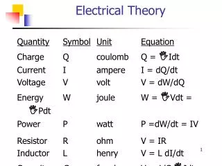
Basic Terminology • Electromotive Force (E or V) • Force which causes electrons to move from one location to another • Known as emf, potential difference, or voltage • Unit is volt (V) • Source: • Generator • Battery • Like pump that moves water through “pressure”
Basic Terminology • Current (I) • Flow of electric charges - electrons (or holes) - through a conductor or circuit per increment of time • Unit is ampere (number of charged particles passing a point each second) • 1 amp = 1 coulomb/sec = 6.02x10²³ electrons/sec • Like rate of flow of water through a pipe
Basic Terminology • Resistance (R) • An electrical circuit’s opposition to the flow of current through it • Measured in ohms (W) • Conductor • All materials will conduct electricity, but at varying resistances • Good conductors have little resistance (ie: silver, copper, aluminum, iron)
Basic Terminology • Insulator • Substances which offer high resistance to current flow (ie: wood, rubber, plastics) • Circuits made of wires covered with insulator • Power (P) • Rate at which work is performed • Measured in watts (W)
Basic Terminology • Direct Current (DC) • Current flow is unidirectional and of constant magnitude (battery) • Alternating Current (AC) • Magnitude & direction of current flow periodically change • Each sequence called a cycle • Frequency is cycles per second (Hz)
Electrical Devices • Rectifier • Converts AC DC • Designed to have small resistance to current flow in one direction & large resistance in opposite direction • Typically called a diode or rectifier
Electrical Devices • Transformer • Device w/o moving parts that transfers energy from one circuit to another by electromagnetic induction • Consists of ferromagnetic core & sets of windings • Step-up: Vin Vout • Step-down: Vin Vout • Only works with AC
Ohm’s Law & Applications • Law: current of a circuit is directly proportional to the applied voltage and inversely proportional to circuit resistance • I a V, I a 1/R V =IR • Power • P = VI P = (IR)I = I2R
Applications • Resistors in Series • RT = R1 + R2 + R3 + . . . • Resistors in Parallel • 1/RT = 1/R1 + 1/R2 + 1/R3 + . . . • Examples: should be able to find total current flow in circuit, current flow through each resistor, voltages, power dissipated, etc.
Kirchhoff’s Laws • Kirchhoff’s Current Law (KCL) • A node is any junction in a circuit where two or more elements meet • Currents into a node sum to zero OR • Current entering a junction is equivalent to the current leaving a junction
Kirchhoff’s Laws • Kirchhoff’s Voltage Law (KVL) • A loop is any path in a circuit that current can take so that it meets back up to where it starts • Voltages around a CLOSED loop sum to zero
Electrical Theory II –The Applications Harnessing the Power…
Introduction • Electromagnetic Induction • DC • Generators • Motors • AC • Generators • Motors • Three-phase AC
How is Electricity Produced? • Friction: “static electricity” from rubbing (walking across a carpet) • Pressure: piezoelectricity from squeezing crystals together (quartz watch) • Heat: voltage produced at junction of dissimilar metals (thermocouple) • Light: voltage produced from light striking photocell (solar power) • Chemical: voltage produced from chemical reaction (wet or dry cell battery) • Magnetism: voltage produced using electromotive induction (AC or DC generator).
Electromagnetic Induction • Faraday (1831): • Showed that an emf is induced in a conductor if a magnet passes by a conductor • When pole of magnet entered coil, current flowed in one direction • When direction of magnet reversed, current flowed in opposite direction
Electromagnetic Induction • Results in: • Generator action: generator converts mechanical to electrical energy • Motor action: motor converts electrical to mechanical energy
Generator Action • For emf/current (electricity): • Magnetic Field • Conductor • Relative Motion b/t the two • Voltage produced: “induced emf/voltage” • Current produced: “induced current” • Left-hand rule for generator action
Motor Action • For motor action (torque/motion): • Magnetic Field • Conductor • Current flow in conductor • Torque produced: “induced torque” • Right-hand rule for motor action
Electromagnetic Induction • Magnitude of induced current can be increased by: • Increasing strength of magnetic field • Increasing speed of relative motion • Positioning of field & conductor to increase number of magnetic lines of flux cut • Magnetic field usually produced by electromagnet
Electromagnet • Soft iron core wound with coils of wire • When current present (excitation current), core becomes magnetized • Field strength determined by number of turns and magnitude of current: B a NIDC
Standard Terminology • Stator: stationary housing of the generator or motor • Rotor: rotating shaft inside the stator • Field windings: conductors used to produce electromagnetic field • Armature windings: conductors in which output voltage is produced (or input is provided)
DC Generators • Basic Principle: rotate a conductor within a magnetic field to induce an EMF • Field windings located on stator & receive current from outside source
DC Generators • Armature windings on rotor • Commutator rings used to mechanically reverse the armature coil connection to the external circuit • EMF developed across the brushes becomes a DC voltage/current (pulsating and unidirectional)
DC Motors • Essentially the same in construction as DC generator • Based on principle that current carrying conductor placed at a right angle to a magnetic field tends to move in a direction perpendicular to magnetic lines of flux • Only need to change relative voltage to go between generator motor
AC Generators • Most electrical power used is AC made by AC generators • Basic principle: rotating magnetic field “cutting through” a conductor • Regardless of size, all AC generators work on same principle • Two types: • Revolving armature (NOT used) • Revolving field (Used in SSTG’s, GTGS, DG)
AC Generators • Two types: • Revolving armature (NOT used) • Revolving field (Used in SSTG’s, GTGS, DG)
AC Generators • Field windings on rotor • DC current provided for field via slip rings and brushes (vice commutator rings) • Rotor turned by prime mover creates rotating magnetic field • Armature windings on stator • As field rotates, AC current produced in armature • Since stationary contacts, no arc-over
AC Generators • Determining speed of AC machine: f= P(RPM)/120 RPM = 120f/P • Must maintain constant 60Hz output use speed governor to maintain constant RPM (independent of loading) • Must also regulate voltage output • Since constant RPM, must control field excitation (DC current) to control output voltage
AC Motors • Use AC current as input to produce work • Many different types depending on number of phases of AC input & construction • Ex: induction motor • Input AC current on stator produces rotating field • Current produced in conductors on rotor produces torque
Three Phase (3f) AC Power • Phases: number of sets of armature windings on stator • 3f has three sets of armature windings • Voltage induced is 120o out of phase for each • Output: 3 sinusoidal voltages and currents • Allows more power to be delivered with a smaller design generator