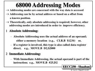
68000 Interface Timing Diagrams
Outline 68000 Read Cycle 68000 Write Cycle Goal Understand 68000 bus cycles Learn how to attach memory, peripherals to CPU Reading Microprocessor Systems Design, Clements, Ch. 4. 68000 Interface Timing Diagrams. 68000 read word from memory 68000 acts as bus master initiates read

68000 Interface Timing Diagrams
E N D
Presentation Transcript
Outline 68000 Read Cycle 68000 Write Cycle Goal Understand 68000 bus cycles Learn how to attach memory, peripherals to CPU Reading Microprocessor Systems Design, Clements, Ch. 4 68000 Interface Timing Diagrams
68000 read word from memory 68000 acts as bus master initiates read Memory acts as bus slave responds to master requests Memory-mapped I/O “memory” can really be peripheral device Interlocked handshaking between master and slave master uses R/~W, AS*, UDS*, LDS* to tell memory that address is present slave uses DTACK* to tell CPU that data is ready A 68000 memory access takes a minimum of eight clock states numbered from clock states S0 to S7 68000 Read Cycle
Not to scale - relationships more important Typically do not care about data/address signal values Do care about control signal values Voltage sensing Vol - maximum logical zero voltage on output Voh - minimum logical one voltage on output Vil - maximum logical zero voltage on input Vih - minimum logical one voltage on input Time delays measured from reference voltage 50%, 10%, 90% of Vdd Timing Diagrams
A memory access begins in clock state S0 and ends in state S7
The most important parameter of the clock is the duration of a cycle, tCYC.
At the start of a memory access the CPU sends the address of the location it wishes to read to the memory
We are interested in when the 68000 generates a new address for use in the current memory access The next slide shows the relationship between the new address and the state of the 68000’s clock Address Timing
In state S1 a new address becomes valid for the remainder of the memory access Initially, in state S0 the address bus contains the old address
The time at which the contents of the address bus change can be related to the edges of the clock.
Let’s look at the sequence of events that govern the timing of the address bus The “old” address is removed in state S0 The address bus is floated for a short time, and the CPU puts out a new address in state S1 Address Timing
The old address is removed in clock state S0 and the address bus floated
tCLAV The designer is interested in the point at which the address first becomes valid. This point is tCLAV seconds after the falling edge of S0.
The memory needs to know when the address from the CPU is valid. An address strobe, AS*, is asserted to indicate that the address is valid.
We are interested in the relationship between the time at which the address is valid and the time at which the address strobe, AS*, is asserted When AS* is active-low it indicates that the address is valid We now look at the timing of the clock, the address, and the address strobe Address and Address Strobe
AS* goes active low after the address has become valid AS* goes inactive high before the address changes
AS* goes low in clock state S2
The 68000 has two data strobes LDS* and UDS*. These select the lower byte or the upper byte of a word during a memory access To keep things simple, we will use a single data strobe, DS* The timing of DS* in a read cycle is the same as the address strobe, AS* The Data Strobes
The data strobe, is asserted at the same time as AS* in a read cycle
During a read cycle the memory provides the CPU with data The next slide shows the data bus and the timing of the data signal Note that valid data does not appear on the data bus until near the end of the read cycle The Data Bus
Data from the memory appears near the end of the read cycle
We are going to redraw the timing diagram to remove clutter We aren’t interested in the signal paths themselves, only in the relationship between the signals Analyzing the Timing Diagram
We are interested in the relationship between the clock, AS*/DS* and the data in a read cycle
The earliest time at which the memory can begin to access data is measured from the point at which the address is first valid
Data becomes valid Address becomes valid The time between address valid and data valid is the memory’s access time, tacc
We need to calculate the memory’s access time By knowing the access time, we can use the appropriate memory component Equally, if we select a given memory component, we can calculate whether its access time is adequate for a particular system Calculating the Access Time
Data from the memory is latched into the 68000 by the falling edge of the clock in state S6.
Data must be valid tDICL seconds before the falling edge of S6
We know that the time between the address valid and data valid is tacc
The address becomes valid tCLAV seconds after the falling edge of S0
From the falling edge of S0 to the falling edge of S6: • the address becomes valid • the data is accessed • the data is captured
The falling edge of S0 to the falling edge of S6 is three clock cycles
68000 clock 8 MHz tCYC = 125 ns 68000 CPU tCLAV = 70 ns 68000 CPU tDICL = 15 ns What is the minimum tacc? 3 tCYC = tCLAV + tacc + tDICL 375 = 70 + tacc + 15 tacc = 290 ns Timing Example
Timing spec references asynchronous signals for memory actions Spec references clock for CPU actions CPU outputs change CPU samples inputs Metastability what if input changes at same time clock samples it? violates setup and hold time specifications sometimes result is undefined sometimes spec says wait a clock cycle in practice input logic can go into metastable state in between 0 and 1 cause other logic to fail design to avoid this situation 68000 Synch/Asynch System
Features address decoder to select RAM 4KB block aligned to 4KB boundary use chip select for byte read/write optionally delay DTACK Chip select 68000 Connected to 6116P-6 SRAM Inputs Outputs Operation AS* RAMCS* UDS* LDS* CS2* CS1* 1 X X X 1 1 Noop X 1 X X 1 1 Noop 0 0 0 0 0 0 Word 0 0 0 1 0 1 Upper byte 0 0 1 0 1 0 Lower byte 0 0 1 1 1 1 Noop
Relate 68000 timing diagram to 6116P diagram Memory access S0 fall to S6 fall = 3 x tCYC address becomes valid (tCLAV), memory accessed (tAA), data setup (tDICL) total memory address access time = tCLAV + tAA + tDICL Memory read for 8 MHz 68000 3 x tCYC > tCLAV + tAA + tDICL tAA < 3 x tCYC - tCLAV - tDICL tAA < 3 x 125 - 70 - 15 = 290 ns 6116P has tAA < 200 ns, so zero wait states Memory read for 12.5 MHz 68000 tAA < 3 x 80 - 55 - 10 = 175 ns need to add a wait state Read Cycle Calculations
Data hold time tSHDI > 0 ns from rising AS* address does not change until rising S0 rising AS*/UDS*/LDS* deselects chip deselect to floating (tCHZ) > 0 ns gate delays ensure spec Chip select/deselect time CS* from AS*, RAMCS*, USD*/LDS* if address decode < 30 ns, then CS* one gate delay after AS* CS* to driver on < 15 ns, long before data available data bus floated tCLSH + tGATE + tCHZ after S7 starts if tGATE = 10 ns, bus floats 70 + 10 + 60 = 140 ns after S7 S7, S0 = 62.5 ns, bus could float 15 ns into S1 okay since next access in S2 Read Cycle Calculations (cont.)
Similar to read cycle Difference CPU puts data on data bus early in bus cycle UDS*/LDS* not asserted until data on bus R/~W is set low most memory needs address stable before this memory/peripheral reads data can use UDS*/LDS* to latch data into memory Timing requirements typically write cycle specs can be easily met memories write faster than they read big driver to little cell vs. little cell to big load 68000 Write Cycle
Used for indivisible operations locks, semaphores, monitors TAS - test and set CAS/CAS2 - compare and swap 68000 keeps address strobe low address bus value same for read and write strobes data for read and write set R/~W high, then low Read-Modify-Write Cycle
Synchronous bus I/O devices and memory also referenced to clock Much simpler timing Many fewer clock cycles per bus transaction Everything referenced to clock See Section 7.5 See ColdFire User’s Manual pg. 17-10 68040 & ColdFire Timing