Download
1 / 61
810 likes | 2.35k Vues
Analysis and Design of a Multi-storey Reinforced Concrete Building. U nited A rab E mirates U niversity C ollege of E ngineering C ivil and E nvironmental E ngineering D epartment G raduation P roject II. Prepared

E N D
Analysis and Design of a Multi-storey Reinforced Concrete Building United Arab Emirates UniversityCollege of EngineeringCivil and Environmental Engineering DepartmentGraduation Project II Prepared Sultan Saif Saeed Alneyadi 200203903 Sultan Khamis AL-shamsi 200101595Hasher Khamis AL-azizi 200106031Rashed Hamad AL-Neyadi 200204018Abdulrahman Abdulla Jarrah 200210915 Adviser Dr. Usama Ebead Second Semester 2007/2008
Outline • Objectives • Summary • General Approach • Building Types • Concrete • Structural Elements • Slabs • Flat Slab • Design of Flat Slab • Columns • Rectangular Columns • Design of Rectangular Columns • Shear walls • Design of Shear Walls • Foundations • Pile Group • Design of Pile Group • Economic Impact • Enviromental Impact • Conclusion
Objectives The Objectives of the Project are:- • Carrying out a complete analysis and design of the main structural elements of a multi-storey building including slabs, columns, shear walls and foundations • Getting familiar with structural softwares ( SAFE ,AutoCAD) • Getting real life experience with engineering practices
Summary • Our graduation project is a residential building in Abu- Dhabi. This building consists of 12 repeated floors.
General Approach • Obtaining an architectural design of a regular residential multi-storey building. • Al-Suwaidy residential building in Abu Dhabi. • Establishing the structural system for the ground, and repeated floors of the building. • The design of column, wind resisting system, and type of foundations will be determined taking into consideration the architectural drawings.
Types of building • Buildings are be divided into: • Apartment building • Apartment buildings are multi-story buildings where three or more residences are contained within one structure. • Office building • The primary purpose of an office building is to provide a workplace and working environment for administrative workers.
Concrete Mixtures • Concrete is a durable material which is ideal for many jobs. • The concrete mix should be workable. • It is important that the desired qualities of the hardened concrete are met. • Economy is also an important factor.
Structural Elements Any reinforced concrete structure consists of : • Slabs • Columns • Shear walls • Foundations
Flat Slab Structural System Flat slab is a concrete slab which is reinforced in two directions • Advantages • Disadvantages
Defining properties • Slab thickness = 23 cm • Concrete compressive strength = 30 MPa • Modules of elasticity of concrete = 200 GPa • Yielding strength of steel = 420 MPa • Combination of loads (1.4Dead Load + 1.6 Live Load)
ACI 318-02 • ACI 318-02 contains the current code requirements for concrete building design and construction. • The design load combinations are the various combinations of the prescribed load cases for which the structure needs to be checked. 1.2 DL + 1.6 LL
Flat Slab Analysis and Design 15 • Analyzing of flat slab mainly is done to find • Shear forces. • Bending moment. • Deflected shape. • Reactions at supports.
Results and Discussion 16 Deflection
Results and Discussion Reactions at supports must be checked by a simple method.
Columns It is a vertical structural member supporting axial compressive loads, with or with-out moments. Support vertical loads from the floors and roof and transmit these loads to the foundation.
Types of column • Tied Columns • Over 95% of all columns in building in non-seismic regions are tied columns • Spiral Columns • Spiral columns are generally circular. It makes the column more ductile. Spiral column Rectangular column
Steel Reinforcement in Columns • The limiting steel ratio ranges between 1 % to 8 %. • The concrete strength is between 25 MPa to 45 Mpa. • Reinforcing steel strength is between 400 MPa to 500 Mpa.
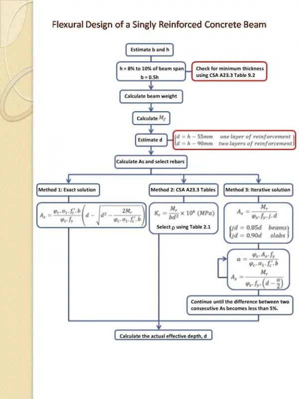
Design procedure 1. Calculate factored axial load Pu 2. Select reinforcement ratio 3. Concrete strength = 30 MPa, steel yield strength = 420 MPa 4. Calculate gross area 5. Calculate area of column reinforcement, As, and select rebar number and size.
Guidelines for Column Reinforcement • Long Reinforcement • Min. bar diameter Ø12 • Min. concrete covers 40 mm • Min. 4 bars in case of tied rectangular or circular • Maximum distance between bars = 250 mm • Short Reinforcement ( Stirrups) • Least of: • (16)×diameter of long bars • least dimension of column • (48)×diameter of ties Asp S dc
Column Design 8- # of bars =
Shear walls • A shear wall is a wall that resists lateral wind loads which acts parallel to the plane of the wall.
Shear walls • Wind results in a pressure on the surface of the building • Pressure increases with height • Positive Pressure, acts towards the surface of the building • Negative Pressure, acts away from the surface of the building (suction)
Wind pressure • q = Velocity pressure • (Wind speed, height and exposure condition) • G = Gust factor that depends on the building stiffness • Cp = External pressure coefficient
Gust G Factor & External pressure Cpcoefficient • for Stiff Structures take G =0.85 • Windward Wall, Cp = +0.8 • Leeward Wall, Cp = varies between -0.2 & -0.5 • Depending on the L/B Ratio • L/B = 18.84 m /26.18 m = 0.719 < 1 then , Cp = -0.5
Velocity Pressure • V = 160 km/h • Kz = To be determined from the equations • Kzt = 1 (level terrain adjacent to the building – not on hill) • Kd = 0.85 (rectangular building) • I = 1 (use group II)
Design of the wind force 34 • North south direction
Calculating Velocity Pressure 36 1 0.85 1 145 km/h
Design of the wind pressure 37 qb = qz (at the top of the building)
Computing total moment acting toward N-S Direction 38 M = total floor level *height (z)
W-E Direction Computation B= 18.84 L= 26.18 39
Design of Shear Wall 40 • East west direction • North south direction
Foundations • Foundations are structural components used to support columns and transfer loads to the underlying Soil. Foundations Deep Shallow Isolated Combined Strap wall Raft footing footing footing footing footing Caissons Piles
Pile cap Piles Weak soil Bearing stratum Pile foundation • Our building is rested on a weak soil formation which can’t resist the loads coming from our proposed building, so we have to choose pile foundation.
Pile foundation • Piles are structural members that are made of steel, concrete or timber.
Function of piles • As with other types of foundation, the purpose of a pile foundation is: • To transmit a foundation load to a solid ground • To resist vertical, lateral and uplift load • Piles can be • Timber • Concrete • Steel • Composite
Concrete piles General facts • Usual length: 10m-20m • Usual load: 300kN-3000kN Advantages • Corrosion resistance • Can be easily combined with a concrete superstructure Disadvantages • Difficult to achieve proper cutoff • Difficult to transport
Pile foundation Piles can be divided in to two major categories: • End Bearing Piles If the soil-boring records presence of bedrock at the site within a reasonable depth, piles can be extended to the rock surface • Friction Piles When no layer of rock is present depth at a site, point bearing piles become very long and uneconomical. In this type of subsoil, piles are driven through the softer material to specified depths.
Pile Cap Reinforcement • Pile caps carrying very heavy point loads tend to produce high tensile stresses at the pile cap. • Reinforcement is thus designed to provide: • Resistance to tensile bending forces in the bottom of the cap • Resistance to vertical shear
Design of the pile cap • bearing capacity of one pile: Rs = α ⋅ Cu ⋅ As .L • Length of pile penetration L = 18 meters • Adhesion factor of soil (clay) α = 0.8 • Untrained shear strength Cu = 50 • Diameter = 0.9 m • For piles with diameter 0.9 m Rs = 2035.75 KN